Locomotive two-current ÖBB, series 1822
Gabriel MOISA
Technical University Cluj-Napoca
Abstract
The paper presents certain nominal and exploitation data about OBB two-current locomotive, alias locomotive from Breeder, of components principal, which contain she (motors 6 FRA 7059, principal transformer, microcomputer MICAS-S2). Is described in detail this principle of function, as well as one command-control system de-centralized MICAS-S2.
It insists about the operation and transit mode from alternate current in continuum current. Are setting off the different protections that are imposed.
Keywords
Command systems, Control systems, European railways.
1. Introduction
The Austrian two-current locomotive from series 1822 was realized under ABB limited. She make the liaison between the continuum current by 3 kV from Italy and the alternate current de 15 kV, 16 2/3 Hz from Austria and German system, with important economic implications.
Because of the locomotives from series 1822 are intended of three countries with different traction systems is desirable to incorporate equally appropriate security and communication systems. This thing, practically, is realized, the mechanic activating the desirable installation group aid of one select switch.
2. Technical Specifications
The Austrian two-current locomotive from 1822 series, so called the locomotive from Breeder was realized under limited ABB, in cadre of an Austrian transport community.
She make the connection between system supply at alternate current by 15 kV and 16∙2/3 Hz (German, Austria) and the continuum current system by 3 kV (Italy). Among her techniques dates can be mentioned that: the traction power is de 4400 kW, some quantity of energy may be recuperate by recuperative breakage, respectively 1000 kW at breakage by resistance.
The maximum start effort is de 280 kN∙m and, in the continuum regime, is 250 kN∙m. Tension at supply can vary in alternate current between 25 % and 20 % and in c.c. between 2 to 4.2 kV. The tension from intermediate circuit is 3500 V in a.c., respectively 2000-4200 V in c.c.
On 3 kV c.c. system the primary current is big, so that the locomotive circulate with two pantographs, situated on her extremity, and in a.c. 15 kV with one. An important component of locomotive two-current is one measure of converter combination who detects the supply system in automating mode, independent of mechanic decisions. Rapid interrupter UR26, with electromagnetic arc extinction, forms the principal automatic circuit breaker in c.c.. He has a switcher electric and an excess currents release indirect commanded, by command technique of static converter. For AC principal automatic circuit breaker was used the interrupter with pressed air DBTF 20i200.
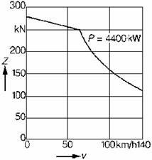
(Z – Torque, V – Speed, P – Power)
Figure no 1. Torque-speed diagram shown by “Brennerlok”
The principal transformer has a primary power by 4640 kVA at a nominal tension by 15 kV. The four windings by secondary (of traction) stick an apparent power by 1009 kVA, 1886 V and 535 A. The transformer dimension, which gives chase to minimize the parasite currents, has a short circuit tension by approximate 20 % on the nominal tension.
The double entrance inductance, assure one total impedance by 2.5 Ω at 50 Hz. that serve to amortization the commutation in case 3 kV c.c. system.
The two windings of entrance inductance are magnetic coupled. Two condensers by absorption circuit with two inductances constitute two absorption circuits for 33∙1/3 Hz. From redundancy motives, each of bogies operated do identical converter blocs supply separating. The two-current locomotive ÖBB, 1822 series is that who used from the first static frequency converter in circuit with three points.
This circuit is characterized by fact that, in intermediate circuit, the central point of continuum tension is accessible. That particular disposition was obtain by series coupling of GTO thyristors. This permit switching in of windings in two iscarry, leading to over-demand of reactance entrance coils.
Simultaneous, the tension variation ramp lesser, assures the isolation. Accordingly was obtained, in equal mode, less of harmonics spectrum in lows speed range.
The system converter has four quadrants and supplies the intermediate circuit with a continuum nominal tension by 3500 V. He admits the maintenance of current by supply with a phase factor and a power factor practical equal with one. In the intermediate c.c. circuit is find a LC filter for 33∙1/3 Hz who form the absorption circuit represent by a smoothing condenser. This accumulates the energy and admits in spite of power pulsate by one-phase system, a regular power for three-phase traction inverter of motors.
The speed regulation of traction motors is realized at a variable tension and variable frequency. Under the portion with alternate current, the energy that result from the recuperative braking can be giving back in supply under at a power by 4400 kW through four quadrant system converter.
The concept of protection CSF is based by principle protection starting. The GTO status is intimated in command unity and the transmission of command apparatus for action. This method prevents the unexpected critic ignitions.
In case of an apparition of a disturber, all the GTO it was transmitted a releasing instruction. If during the breakage result an increase of tension in intermediate circuit, is connected automaton a resistance for deviation of supplementary energy, before exceed of admissible blockage tension of semiconductors devices. The protection concept is subdivided hierarchical in five degrees, according to the repercussions by system. In normal conditions by exploitation, the inferior protection degree is permanent in service, the exploitation of locomotive being maintenance.
The superior protection degree is not used, than in case of the serious dangers and challenge the complete releasing of redresser under the bogie.
In series of locomotives 1822 is used the direct auto-regulation procedure. Thus, starting of tension parameters, current and speed of motor, the system will calculate the magnetic flux and the effective torque and compare them with the impose value.
The torque regulator no product than the requirement torque orders “yes” or “not”. All the regulation processes are displaying in the interior of a tolerance band very straiten, with a maximal tact frequency. This procedure is possible grace of microcomputer MICAS-S2. Is using cage three-phase induction motors, with six poles, in execution mode less of rotor protection envelope.
The nominal data (who can be permanently maintained) are the power: 1105 kW, the tension among phases: 2190 V, the intensity: 364 A, the maxim intensity: 434 A, the nominal rotation speed: 1300 rpm, at 66 Hz, and the maxim: 2900 rpm, at 148 Hz.
Are commanded, regulated and supervised by the command-control system MICAS-S2 the locomotives.
The different electronics modules are situated in center of users and connected at vehicle bus of MICAS system, which reduce very much the number of cables.
The system makes a very good change among the electronics and the digital signals.
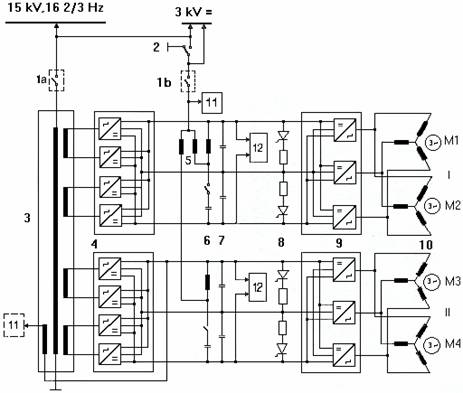
Figure no 2. The principal electric circuit of
locomotive two-current ÖBB, Series 1822
Legend for figure 2:
I - Bogie 1;II - Bogie 2
1.a. The principal automate circuit breaker, for alternate current exploitation
1.b. The principal automate circuit breaker, for continuous current exploitation
2. System commuter
3. Transformer
4. Four quadrants network converter
5. Double entrance inductance
6. Absorption circuit
7. Smoothing condenser
8. Braking resistance
9. Inverter
10. Traction motors (M1-M4)
11. Warming
12. Converter from supply network
A vehicle command-control apparatus is taking the entire command functions locomotive. Is word about the imposed values of traction and braking, of speed regulation, for auxiliary services, during any command are unrolling. The communication among the command-control apparatus is making by short and big distance buses. The short distance buses assure the communication in inter of a module.
The big distance buses connect different bus stations by optic fibers, which permit the transmission of data with a 1.5 Mb/sec speed. The vehicle bus is optimized for a cyclic transfer. The data can be divided with transmission according of their priority in date of: procedure, service and diagnostic.
The last are transmitted to one bus station of diagnostic computer, provided with a hierarchical memory.
Data traffic at vehicle bus is coordinated by a bus central gestation, who invites each of signal sources to emit accordingly her cycle time. The signal receivers and the programs for these sensors retain the bus data, treating by their application programs and emitting the concordant signals to a procedure.
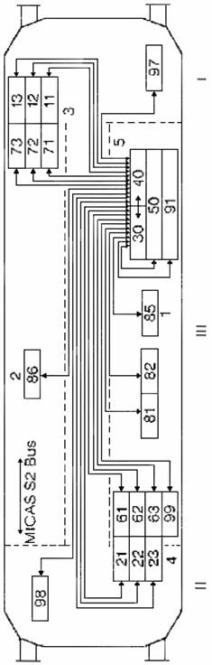
Figure no 3. Schema of electronic command-control MICAS-S2
Legend for figure 3:
I: Pilot post 1;
II: Pilot post 2;
III: Machine room;
1, 2: Principal electric cupboard 1 and 2;
3, 4: Electric cupboard from machine room;
5: Electronic cupboard;
11, 12, 13: Bus station of pilot post 1;
21, 22, 23: Bus station of pilot post 2;
30, 40: Vehicle command-control apparatus 1 and 2 (fiber optic conductors / radial connection);
50: Extern electronic;
61, 62, 63: Bus station of auxiliary blocs;
71, 72, 73: Bus station of current command blocs;
81, 82: Supply network converter;
85, 86: Electronic of inverter 1 and 2 (apparatus of converter and of traction command);
91: Tachometric installations;
97, 98: Screen 1 and 2;
99: Braking computer;
Each bus component transmits, therefore, directly its data for signal receivers. The diagnostic computer, upper specified, supervise and compare the effective values provided by peripheral apparatus, with the imposed values. In case off divergent and troubles, is storage the concordant data.
These are displayed on screen of conduct post, which can be taking over and treated by means of a service interface.
The command-control technique of locomotive is conceived for a multiple command.
The data change between vehicles is making by approximation of train bus. The interface is based by command principle, by multiplexage.
The transmission media is provided by UIC line.
3. Conclusions
The studies about these locomotives in different situations (start, pace, breakage, transit between different supply systems, influence of the towed load and of en route ramp that touch 26 ‰ where are used) as well as can be pursued the attitude (simultaneous) in other traction systems different of the national systems present a certain interest in study of others two-current locomotives which make the transition between others traction systems, different the presenting system in paper.
References
Peter Jahn, Hervig Leichtfried – Revue ABB 4/92, p. 15-22.