The Integrated Development System for Vehicle Control based on
Seamless Connection between Hard and Software Implementation
Xin ZHANG
ChangSha University of Science & Technology
E-mail: zxxbzjy@sina.com
Abstract
This paper, establishes a complete vehicle model in MATLAB/Simulink development environment, constructs a vehicle control application using Stateflow, Generates C source code for a microcontroller with Real Time Workshop, builds object code for target CPU, develops an efficient seamless development system used in real-time hardware in the loop system, and validates the system practical performance at the final stage by the implementation of vehicle ABS system.
Keywords
Development System, Vehicle Control, ABS System, Real-time Hardware Simulation
1. Introduction
Driven by the trend that the vehicle electronic systems are becoming more and more complex and the competition is becoming more and more intense, the product development period has been dramatically shortened and the requirements to development strategies have been much stricter than before. This has made it very important to use even more advanced development tools. Conventionally, the appropriate control algorithm is determined by simulation, implemented in microcontrollers, and validated by road testing at the final stage prior to which some inside benchmark tests might be included. Although it is true that quite a few good control algorithms are obtained through a large amount of real vehicle road tests, this process certainly consumes a long time period. Recent years some rapid prototyping systems for control system and real-time hardware-in-the-loop systems appear which have significantly increased the development efficiency and shortened the developing time. However, because the final target microcontroller is not the same as the CPU used in development process, most of the control algorithm code is still hand-written. This is what the development limitation is. The control system software MATLAB/Simulink, which is well known for simulation and controller design, is also suitable for the design and research for vehicle control applications. What is more important, it has large quantity of resources to be exploited due to its modelization and visualization, and the vehicle model and control applications built by this software have good reutilization and maintainability. The Real Time Workshop (RTW) toolbox of MATLAB can convert Simulink blocks and Stateflow diagrams into PC-based C source code, which has a difference lap to the final stage microcontroller-based code. Recently some famous company such as dSPACE begins to combine development with simulation to deal with Simulink blocks by directly using software (Target Link) so as to automatically generate C source code for microcontrollers. However, the flexibility is not so satisfying because all these kind of software are used for special purpose, the types of their target controllers are limited, their price is very high and also they must match with the hardware. Therefore, it has dramatic significance to establish a versatile development system integrated with a microcontroller. This paper describes the preliminary trial in this field which intend to construct an integrated development system for Infineon C164 16-bit microcontroller and MATLAB/Simulink, and at the same time combine real-time simulation system to establish a simplified, economic and practical development system for vehicle control system.
2. Development Process for Vehicle Control System
The concurrent prevalent development process for vehicle control applications is V-cycle based designed process as shown in Fig. 1, which includes following five phases.
Fig.1 Design Cycle for Control Applications
System Design and Offline Simulation
The goal of this step is to specify the desired system behaviour and use MATLAB/Simulink software to create a controller and vehicle models. Designers can do offline simulation and study various control algorithms to look for reasonable algorithm in this step.
System Prototype Complementation
The aim of this step is to generate real-time C code from Simulink block diagrams and run it in an advanced PC computer. The I/O ports for the system can be added to the simulation system. Using RTW toolbox in MATLAB paying no regard of code length can generate the executable target code and efficiency because advanced PC has been used. Then it could run in local PC for real-time algorithm validation.
Generate C Code for Target Microcontroller
This is a very hard step in the design process for a long time because the reasonable algorithm obtained in the prior two steps must be transferred in hand written code, which is rather time-consuming and error-prone. However, if the code for target CPU is generated directly from Simulink block diagram, the design process at all stages could be connected seamlessly. That is what this paper introduced. At this stage C code for a microcontroller is generated from Simulink blocks and algorithm is downloaded into a microcontroller.
Hardware-in-the-Loop Simulation
A controller is linked to real-time hardware simulation system in this step. The data can be exchanged between the simulation system and the controller through hardware signals. In our system, the vehicle model in the simulation system is realized with Simulink blocks. The I/O driver for data acquisition card is built by in lining S function. Both the soft- and hardware for the controller can be validated thoroughly during this period. And at the same time large amount of inner data in controller side can be transferred outside through the dual-port RAM in microcontroller emulating system and be demonstrated in real time in PC computer.
System Validation and Calibration
In this step controller can be validated in real vehicle road tests. And control parameters are calibrated to compensate the differences between real vehicle and its model. Meanwhile, control algorithm and vehicle model can be further improved in the Simulink environment so that the controller can reach the production level.
All the above five steps could not be separated because they are combined organically. The advantage of this design process is that every step can be used by another step next to it, the transition from one step to another is seamless, and the task for every step can be completed in very short time. At mean time results obtained in latter step can feed back to former one, which makes the system even more complete. Without hand coding the developing process can dramatically save time. This is the key for the solution.
3. An Example Implementation:
A Vehicle Anti-lock Braking System (ABS) Development
The prerequisite for this application is that there is high enough processing speed and large enough program space, which are demands more than 8-bit or lower 16-bit microcontroller. Here in this system the 16-bit microcontroller from Infenion C164 is used. It has an innovative architecture with four-level pipeline operation, and 16 MIPs (in 20MHz CPU rate) computing speed, which can partly fulfil the demand of floating point data computing. The C compiler and linker are from Tasking Inc. And the emulator is a dual-port RAM architecture. C source code generated from RTW is compiled and linked and then converted into Intel Hex format file which at last stage is downloaded into program memory by the emulator and run in the microcontroller.
To implement this real-time simulation system, a development system for vehicle ABS is constructed, among which the vehicle model is shown as Fig. 2. The I/O interface is built with S function which acquisition data in fixed sampling rate. The input data to the model is the control command or modulator signals from ABS controller (ECU) acquisited by the I/O interface. Meanwhile through the I/O hardware vehicle model send the vehicle dynamic status in form of square waves signal to simulate wheel sensor signals. As the code running in target CPU, the ABS controller is connected with the acquisition card by hardware to receive wheel speed pulse signals which are then captured by the capture units of the microcontroller. At the same time the parallel interface port sends output control signals.
As an important part of the system, the implementation of ABS logic will be described in details as following. The ABS control system is built with Simulink/Stateflow utility. Using finite state machine theory Stateflow is a powerful graphical design and development tool for complex control and supervisory logic problems. It allows designers to use flow diagram notation and state transition notation seamlessly in the same Stateflow diagram to effectively represent code structures like for loops and if-then-else constructs in advanced computer languages and achieve a clear, concise descriptions of complex system behaviour. Using Stateflow designers could not only rapidly construct and simulate complex interactive system and supervisory logic but also easily modify the design, evaluate the results, and verify the systems behaviour at any stage of the design until satisfying system performance is obtained. Since most of ABS logic is based on road tests, the control logic is built using if-then structure. That is why Stateflow is the most suitable tools for the design of ABS control logic. Fig. 3 shows the detail Stateflow architecture for the logic algorithm of ABS controller, in which the input parameters reference skip ratio (SR) and wheel angular acceleration/deceleration threshold (ap) act as the control variables and the output parameters are electric-magnetic valve signal (duo) and pressure modulating state value (st). Then the output values are fed back to vehicle model to complete a close-in-the-loop control system.
From Fig. 3 it can be seen that the whole Stateflow chart is built as parent-child mode. In the parent state (named Pressure) there are two child states respectively named P_state (Numbered 1) and P_logic (Numbered 2) which have parallel (AND) relationship.
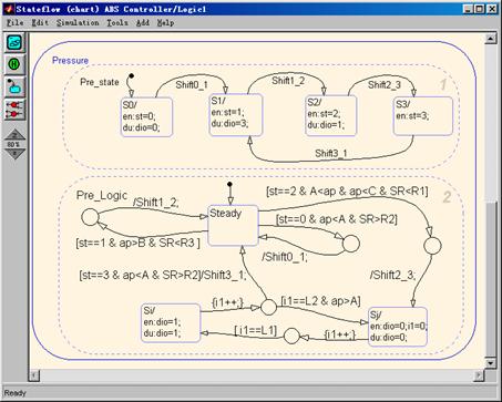
Fig. 3 Stateflow Chart for ABS Logic Control Process
This architecture not only realizes anti-block braking performance but also make the complex logic control process very clear, reasonable and can be easily viewed and adjusted. According to anti-block braking control strategies the four braking steps for ABS control are respectively represented as four pressure modulating states: S0 (Pressure increasing state), S1 (Pressure decreasing state), S2 (Pressure keeping State) and S3 (Pressure small-step increasing state). S0, S1 and S2 are steady states which are represented in P_logic state while S3 is non-steady state which includes two child states S31 and S32 respectively corresponding to the pressure increasing and keeping control states in the small-step process. The time that S1 and S2 states last in a single small-step cycle is determined by parameters L1 and L2. Altering the values of L1 and L2 can modulates the pressure increasing gradient in small-step cycles. The parameters A, B and C are used to configure angular acceleration thresholds which determine the transition between the four pressure modulating states. During the running process of this chart model, state related during (abbreviated as du) actions are executed to set various values to valve signal duo so as to modulate the pressure in the braking pipes and realize anti-block braking function. With the reference skip ratio thresholds more concise anti-block braking logic and more satisfying system performance can be achieved.
From above description it is known that the algorithm for controller established in MATLAB considers only the software part of the controller and does not include any hardware operation. So the hardware system must be initialized and embedded into the generated C source code using RTWs Custom Code tools.
4. Conclusion
This paper incorporates MATLAB simulation environment into target microcontroller system and establishes an innovative development system for vehicle control applications. Being able to apply to the development for other vehicle control applications, this system is also a versatile one features:
· integrated real-time hardware-in-the-loop simulation system;
· executable code for microcontroller can be automatically generated;
· seamless connection between simulation and system implementation.
This system is still a rough one to some degree and has the potent to be further improved in following facts:
· target C code can be further optimized;
· generate more versatile C code and design automatic system especially for hardware peripheral port;
· build development system for more kinds of CPUs.
References
1. CHENG Jun, Theory and Practices for ABS, Press of Beijing Institute of Technology, 1999 (in Chinese).
2. The MATHWORKS, Inc. STATEFLOW®, For Use with SIMULINK, Users Guide Version 2, 1999.
3. The MATHWORKS, Inc. Real-Time Workshop®, For Use with SIMULINK, Users Guide Version 3, 1999.
4. Lutz Koester, Automatic Code Generation for the TriCore Architecture from Infineon Technologies, Embedded Intelligence, Nuremberg, 2000.
Note
Zhang xin, male, Born in 1966, associate professor, Get the PhD of Central South University on 2000, from 2000 to 2002, work at ZheJiang University as Postdoctoral. The research project was Anti-lock Braking System R&D.
Address: No 45 Chiling Road, Changsha Hunan China, Postcode: 410076
Changsha University of Science & Technology
College of Automobile & Mechanical Engineering