Simulation Study of the Fracture Characteristics of Locally Fabricated Aluminium Bar used as Connecting Rod in Vibratory Sieves
Vincent Obiajulu OGWUAGWU
Mechanical Engineering department, Federal University of Technology, Minna, Nigeria
Abstract
A numerical simulation of the fracture characteristics of locally fabricated aluminium bars used as connecting rod in vibratory sieving machines is presented. In the numerical study, commercial purity aluminium was used. The results obtained show a good correlation with the performance of these bars while in service.
Keywords
Fracture, Connecting Rod, Crank, Casting Vibratory sieve
Introduction
One of the major problems facing developing economies is that of engineering material development and processing, and as such, Nigeria is not an exception. The evolution of modern and appropriate agricultural machines for food crop processing in the country has been hampered as a result of non availability of appropriate engineering materials and processing facilities. Major efforts tailored towards developing such machines as grain threshing machines, vibratory sieves etc. have not yielded any remarkable good results due to the unavailability of the right material as well as appropriate processing facilities and technology.
In the fabrication of vibratory sieving machine for example, a common approach is to resort to locally cast rectangular bar using commercial purity aluminium alloy to as crank for the reciprocating motion. These bars more often than not, fail mainly by fracture. This trend has motivated the present study, theoretical simulation of the fracture characteristics of such connecting rod bars.
The conservation laws of elasticity and fracture mechanics have been extensively applied in the fracture analysis of homogenous isentropic and orthotropic materials (Yau et al (1980) and Wang et al (1980). Some numerical methods are available for the analysis of both two- and three-dimensional analysis and simulation of fatigue crack growth and these include the finite element and boundary element methods (Martha et al, (1993), Dhandt, (1998) and Gerstle et al, (1989)). A very common method of the finite element method is the finite element alternating method (Osher and Sethram, (1988) and Vijayakumar and Alluri, (1981).
Mathematical Model
Figure 1 show an aluminium bar typically employed in reciprocating motion for some common sieving machines fabricated locally within the country. The stress displacement relations near the crack tip as a function of r and θ are given as:
|
|
(1) |
|
|
(2) |
|
|
(3)
|
|
|
(4) |
|
|
(5) |
where KI is the stress intensity factor associated with mode I loading. The interest is usually to determine the kink angle resulting from an in-plane symmetry loading of the crack.
In the direction of crack propagation, the maximum hoop stress occurs when
σrθ = 0, where
|
|
(6) |
with
|
|
(7) |

Figure 1. Model of aluminium bar used as connecting rod in reciprocating motion
Numerical Simulation
In the numerical simulation, the properties of commercial purity aluminium were used. This was adopted since the bars are usually cast from these materials.
Results obtained from the numerical simulation are shown in figures 2 to 7. In the Figure 2 is shown the variation of crack size with loading frequency while figure 3 shown the variation of crack size with flaw size. Figure 4 show the variation of stress intensity factor with number of cycles of loading and figure 5 show the variation of stress intensity factor with flaw size. The rates of change of crack size with respect to number of cycles of loading and initial flaw size are shown in figures 6 and 7 respectively.
|
Crack size (mm) |
|
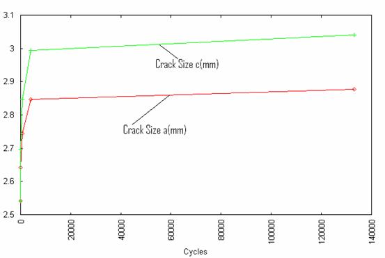
Figure 2. Variation of crack size with number of cycles N
|
Crack size (mm) |
|
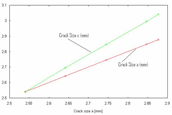
Figure 3. Variation of crack size with crack size a
|
Kmax MPamm½ |
|
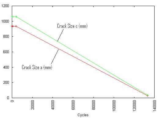
Figure 4. Variation of Kmax with number of cycles N
|
Kmax MPamm½ |
|
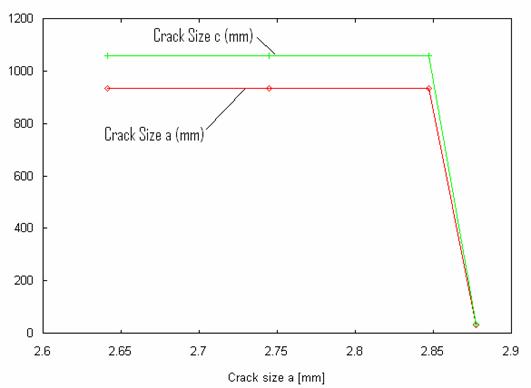
Figure 5. Variation of Kmax with crack size a
|
da/dN (mm/cycle) |
|
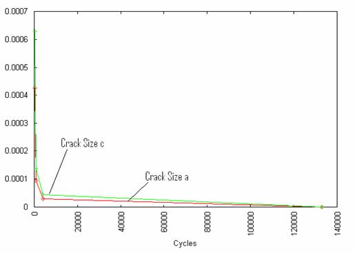
Figure 6. Rate of change of crack size with number of cycles N
|
da/dN (mm/cycle) |
|
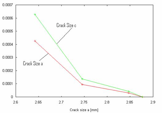
Figure 7. Rate of change of crack size with crack size a
The specimen exhibits an initial deep crack growth curve at the initial cycle of loading and then increased gradually at a steady rate as shown in figure 2. The relation between the initial flaw size and subsequent crack growth is linear, as shown in figure 3.
From figure 4, the value of stress intensity factor decreased steadily at a fairly rapid rate as the number of cycles of loading increased. However, this value remained constant for initial flaw size up to about 2.25 mm and then dropped rapidly to a very low value as shown in figure 5.
There is a rapid rate of change of crack size with respect to number of frequency of loading and initial flaw size as shown in figures 6 and 7.
Although these results were obtained assuming commercial purity aluminium alloy properties, it is pertinent to note here that since these components are not usually treated properly after casting by these foundry artisans, the bars are liable to fail prematurely while in service. This explains the high rate of failure usually experienced while using these machines.
Conclusions
From the results obtained from this numerical study, it is obvious that machine components produced locally by casting by these foundry artisans needs to be properly treated if they are to perform well in service. This would in turn increase people’s confidence in patronizing these local foundry artisans.
References
1. Yau J. F., Wang S. S., Corten H. T., A mixed-mode crack analysis of isotropic solids using conservation laws of elasticity, Journal of Applied Mechanics, 1980, 47(2), p. 335-341.
2. Martha L. F., Wawrzynek P. A., Ingraffea A. R., Arbitrary crack representation using solid modeling, Engineering with Computers, 1993, 9, p. 63-82.
3. Wang S. S., Corten H. T., Yau J. F., Mixed-mode crack analysis of rectilinear anisotropic solids using conservation law of elasticity, International Journal of Fracture, 1980, 16(3), p. 247-269
4. Dhondt G., Automatic 3-D mode I crack propagation calculations with finite elements, International Journal of Numerical Methods in Engineering, 1998, 41(4), p. 739-759.
5. Gerstle W. H., Martha I., Ingraffea A. R., Finite and boundary element modeling of crack propagation in two- and three-dimensions, Engineering Computations, 1987, 2, p. 167-183.
6. Osher S., Sethian J. A., Fronts propagating with curvature-dependent speed: algorithms based on Hamilton-Jacobi formulation, Journal of Computational Physics, 1988, 79(10), p. 12-49.
7. Vijayakumar K., Athuri S. N., An embedded elliptical flaw in an infinite solid, subject to arbitrary crack-face traction, Journal of Applied Mechanics, 1981, 48, p. 88-96.