Investigating the Capability of Power Flow Regulation by Unified Power Flow Controller (UPFC) in a Single-Machine-Infinite Bus System
Mark Ndubuka NWOHU
Department of Electrical/Computer Engineering, Federal University of Technology, Minna, Nigeria
Abstract
The capability of regulating power flow in Nigerian Grid System using UPFC is the main focus in this paper. Consequently, three control methods, namely, voltage control through shunt compensation, real power flow control through quadrature voltage injection and reactive power flow control through in-phase voltage injection for the UPFC were examined in order to improve the transient stability of the power system. The quadrature voltage control was found to be effective in reducing the transient swings whereas in-phase voltage control was effective in improving the transient stability margin. Finally, the overall performance of the UPFC was evaluated in a single-machine infinite bus system by nonlinear simulations, and results obtained showed the effectiveness of the controller in improving the dynamic stability of the system and provide better damping to electromechanical oscillations.
Keywords
UPFC; FACTS devices; Single-Machine-Infinite Bus; Power System; Transient Stability
Introduction
Unified Power Flow Controller (UPFC) is one of the FACTS devices, which can control power system parameters such as terminal voltage, line impedance and phase angle. Therefore, it can be used not only for power flow control, but also for power system stabilizing control [1]. Unified Power Flow Controllers are capable of directing real and reactive power flows through a designated route and regulating the system voltage through reactive power compensation. Thus, UPFC provides several features for power flow control namely: voltage control through shunt compensation, real power flow control through quadrature voltage injection and reactive power flow control through in-phase voltage injection [2]. Hence, the capability of transmission facilities can be better utilized. The mechanism of these three control methods of UPFC in improving the transient stability of the power system will be examined.
However, some works have been done on various control methods for the UPFC and documented in literature by some authors. Smith and et al. [3] proposed decoupled control algorithms of the two components of UPFC series voltage which are quadrature and in-phase with the line current, by active and reactive power respectively. The decoupled control algorithms are based on approximate relationship. Ref. [4] also proposed that the shunt compensation of UPFC is controlled to maintain the system bus voltage. Furthermore, the authors asserted that the two components of UPFC can be controlled in coordination by Strip Eigenvalue Assignment method. Bialek, et al. [5] in their own view, presented an approach based on the use of the nonlinear system model and application of the direct Lyapunov method to improve damping of power swings using the unified power flow controller. They derived a state-variable control strategy using locally available signals of real and reactive power. Chang and Hsu [6] developed a systematic approach based on the root locus method and pole assignment to reach proper proportional-integral (PI) controller gains for the UPFC control system in order to improve system dynamics performance under disturbance conditions.
This paper, however, investigates the three control methods, namely, voltage control through shunt compensation, real power flow control through quadrature voltage injection and reactive power flow control through in-phase voltage injection for the UPFC in order to improve the stability of the power system, thus providing the security for the increased power flow.
Power System Model with UPFC
A simple power system is chosen and studied in PSCAD/EMTDC environment in order to evaluate the performance of the UPFC with different control strategies. The power system whose parameters are given in appendix comprises a 100MVA, 16.64kV synchronous generator connected to an infinite bus through a transmission line and a transformer stepping up the voltage to 330kV. The generator is assumed to have Automatic Voltage Regulator (AVR) controlling its terminal voltage. The single-machine infinite-bus (SMIB) system used in this study is for better understanding of transient stability of Nigerian Grid System since the purpose for the use of UPFC is to improve transient stability of the system. The UPFC is placed between bus 2 and bus 3 on the transmission line as shown in Figure 1. The UPFC is designed to control the power (real and reactive) through line as well as the voltage at bus 3 using PWM power controller.
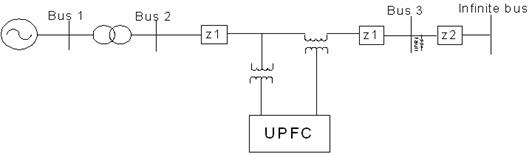
Figure 1. Single-machine infinite bus system with UPFC
Generator model
A detailed dynamic generator model for the single-machine infinite bus system is used for a UPFC controller design to give more accurate controller parameters. It is given as follows [7, 8]:
Mechanical equations:
|
|
(1) |
|
|
(2) |
|
|
(3) |
where ![]() ;
; ![]() is the power angle of the generator;
is the power angle of the generator; ![]() is the power
angle of the generator at the operating point;
is the power
angle of the generator at the operating point; ![]() is the relative speed of the
generator;
is the relative speed of the
generator; ![]() is the mechanical input power (assumed
constant);
is the mechanical input power (assumed
constant); ![]() is the real power delivered by the
generator;
is the real power delivered by the
generator; ![]() is the synchronous machine speed; Dm
is the per unit damping constant; H is the inertia constant.
is the synchronous machine speed; Dm
is the per unit damping constant; H is the inertia constant.
Generator electrical dynamics:
|
|
(4) |
where ![]() is the transient Electromotive force
(EMF) in the quadrature axis of the generator; Eq(t) is the EMF
in the quadrature axis; Ef (t) is the equivalent EMF in the
excitation coil;
is the transient Electromotive force
(EMF) in the quadrature axis of the generator; Eq(t) is the EMF
in the quadrature axis; Ef (t) is the equivalent EMF in the
excitation coil; ![]() is the direct axis open-circuit
transient time constant.
is the direct axis open-circuit
transient time constant.
Electrical equations:
|
|
(5) |
|
|
(6) |
|
|
(7) |
|
|
(8) |
|
|
(9) |
|
|
(10) |
|
|
(11) |
where ![]() is the transient Electromotive force
(EMF) in the quadrature axis of the generator; Eq(t) is the
EMF in the quadrature axis; Q(t) is the reactive power; If(t)
is the excitation current; Iq(t) is the quadrature axis
current; xad is the mutual reactance between the excitation
coil and the stator coil; xd is the direct axis reactance of
the generator; xd׳ is the direct axis transient reactance of the generator; xds׳ is the mutual transient reactance between
the direct axis of generator and transformer; δ(t) is the power
angle of the generator; xds is the mutual reactance between
the direct axis of generator and transformer; xT is the
reactance of the step up transformer; xE is the
reactance of the Thevenin equivalent viewed from bus
is the transient Electromotive force
(EMF) in the quadrature axis of the generator; Eq(t) is the
EMF in the quadrature axis; Q(t) is the reactive power; If(t)
is the excitation current; Iq(t) is the quadrature axis
current; xad is the mutual reactance between the excitation
coil and the stator coil; xd is the direct axis reactance of
the generator; xd׳ is the direct axis transient reactance of the generator; xds׳ is the mutual transient reactance between
the direct axis of generator and transformer; δ(t) is the power
angle of the generator; xds is the mutual reactance between
the direct axis of generator and transformer; xT is the
reactance of the step up transformer; xE is the
reactance of the Thevenin equivalent viewed from bus ![]() ; VE is
the voltage magnitude of the Thevenin equivalent viewed from bus
; VE is
the voltage magnitude of the Thevenin equivalent viewed from bus ![]() .
.
UPFC model and control strategies
The mathematical UPFC model was derived with the aim of being able to study the relations between the electrical transmission system and UPFC in steady-state conditions. The basic scheme of this model is shown in Figure 2.
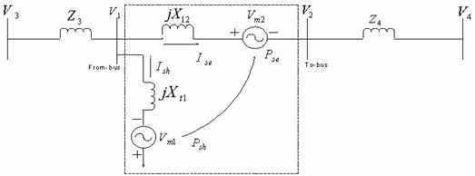
Figure 2. Model of UPFC
The mathematical UPFC model was derived with the aim of being able to study the relations between the electrical transmission system and UPFC in steady-state conditions. The basic scheme of this model is shown in Figure 2. This figure represents a single-line diagram of a simple transmission line with impedance, UPFC, sending-end voltage source and receiving-end voltage source. According to Figure 3, the power circulation and the line flow are calculated by the following expressions [9]:
|
|
(12) |
|
|
(13) |
|
|
(14) |
where Psh is the power at the shunt side of the UPFC; Pse is the power at the series part of UPFC; PL is the real power flow; QL is the reactive power flow; V2 is the voltage at the bus2;
Vm2 is the series voltage of UPFC; V1 is the voltage at bus1; Xt2 is the reactance between buses 1 and 2; θ1and θ2 are the angles of buses 1 and 2 respectively.
The vector diagram of the UPFC is as shown in Figure 3 [10].
Figure 3. Vector diagram of a UPFC connected to a network
The vector diagram of an UPFC connected to a network
(Figure 2) is presented in Figure 3. According to Figure 3, ![]() and
and ![]() are the
components of the series voltage of UPFC. They are proportional to the voltage
at the point of connection of UPFC and can be written as:
are the
components of the series voltage of UPFC. They are proportional to the voltage
at the point of connection of UPFC and can be written as:
|
|
(15) |
where ![]() and
and ![]() are the control variables.
The following equations are deduced from figure 3:
are the control variables.
The following equations are deduced from figure 3:
|
|
(16) |

Multiplying (16) by V2, (17) will be obtained:
|
|
(17) |

The partial derivatives of P2 and Q2 are calculated as (18) and (19) respectively:
|
|
(18) |
|
|
(19) |


Therefore, modulation controller for series-injected
voltage can be designed by using (18) and (19). The value of K is chosen so
that the injected series voltage remains at its nominal value. The values of V2
and V3 can be chosen as 1.0 per unit (p.u.). The
injected series voltage, ![]() is calculated as:
is calculated as:
|
|
(20) |

UPFC can be controlled in a variety of ways to meet different objectives. Basically, UPFC has two different control strategies, namely, (1) series compensator consisting of series inverter and series transformer modeled as a fully controllable voltage source which controls the real and reactive power flow through the transmission line. (2) Shunt compensator comprising shunt inverter, shunt transformer and connection filter modeled as a fully controllable voltage source with connection impedance including the leakage of the shunt transformer [11].
The series inverter provides the main function of the
UPFC by injecting a voltage with magnitude![]() , which is controllable and a
phase angle
, which is controllable and a
phase angle ![]() in series with the line via an
insertion transformer. This injected voltage acts essentially as a synchronous
ac voltage source. The transmission line current flows through this voltage
source resulting in a reactive and active power exchange between itself and the
ac system. The inverter generates the reactive power exchanged at the ac
terminal internally [12]. The active power exchanged at the ac terminal is
converted into dc power, which appears at the dc link as a positive or negative
real power.
in series with the line via an
insertion transformer. This injected voltage acts essentially as a synchronous
ac voltage source. The transmission line current flows through this voltage
source resulting in a reactive and active power exchange between itself and the
ac system. The inverter generates the reactive power exchanged at the ac
terminal internally [12]. The active power exchanged at the ac terminal is
converted into dc power, which appears at the dc link as a positive or negative
real power.
The basic function of shunt inverter is to generate or absorb the real power demanded by series inverter at the common dc link. The power demand by the series inverter at the dc link is converted back to ac by the shunt inverter and fed to the transmission line bus via a shunt-connected transformer. In addition to this the shunt inverter can also generate or absorb controllable reactive power if desired and thereby provides independent shunt reactive compensation for the line [13].
Simulations
To test the effectiveness of the UPFC controller, a balanced three-phase fault is applied to the line at the end close to bus 3 (see Figure 1) at 5.0s when the generator is operating at its rated power level. The duration of the fault is 0.10s. The system responses are simulated using PSCAD/EMTDC [14]. Figures 4 to 12 show the system responses with and without UPFC. It can be observed from these figures that the UPFC with coordinated controller can greatly improve the damping of the system and its stability.
The equations used in the simulation were from 1 to 11 and 13 & 14.
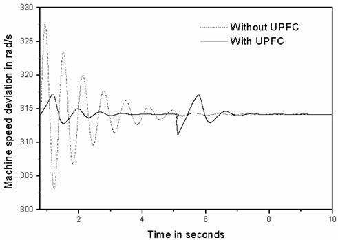
Figure 4. Speed response of the synchronous generator operating for a three-phase short circuit at end close to bus 3
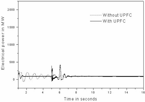
Figure 5. Electrical power output response of the synchronous generator operating for a three-phase short circuit at end close to bus 3
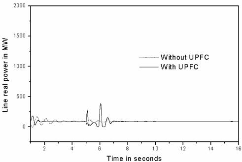
Figure 6. Transient corresponding to line real power
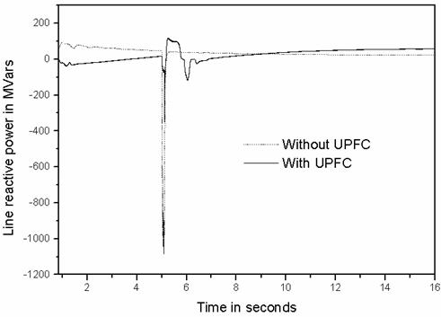
Figure 7. Transient corresponding to line reactive power.
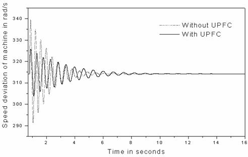
Figure 8. Speed response of the synchronous generator by quadrature voltage control
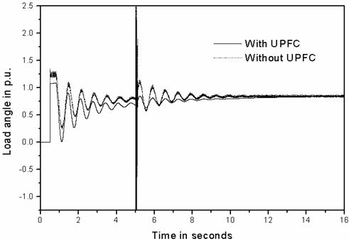
Figure 9. Load angle response of the synchronous generator at quadrature voltage control
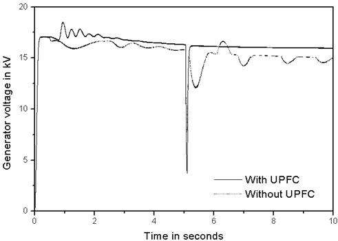
Figure 10. Terminal voltage response of the synchronous generator by quadrature voltage control
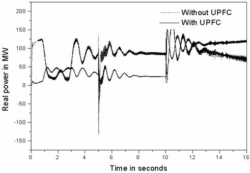
Figure 11. Transient corresponding to line real power by quadrature voltage control
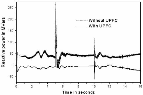
Figure 12. Transient corresponding to line reactive power by quadrature voltage control
Findings and Discussion
Under Shunt Compensation
The simulation results of shunt compensation are shown in Figure 4 to Figure 7.
It is observed that the dynamic oscillations in Figure 4 are well damped when UPFC is connected to the system, although they have large first swing after the fault is cleared.
From Figures 6 and 7, it can be seen that the real and reactive power could be controlled to a specific value after the fault is cleared, which shows that the UPFC is very effective in line flow control.
This, of course, limits the electrical power output of the generator (see Figure 5) which makes the rotor angle increase more than that when there is no UPFC.
Under Series Compensation
The two components of series compensation control are considered with respect to the injected voltage. These components are in-phase voltage and quadrature voltage.
The simulation results of the quadrature voltage control are as shown in Figures 8 to 12. It is observed that the transient swings are reduced, but it is poor in load flow control and damping control.
However, from the equal area criterion, it can be predicted that after the rotor angle reaches the maximum value in the first swing, this control strategy should be changed and should be aiming at damping of the subsequent swings.
But, with in-phase voltage control, the transient stability margin is significantly improved (see Figure 13).
It is noteworthy that the in-phase component contributes to the real power exchange between the series and shunt branch of the UPFC, and reduces the fluctuation in capacitor voltage at its zero value.
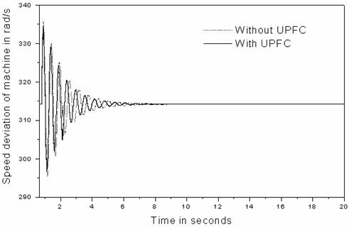
Figure 13: Improved transient stability margin by in-phase voltage control.
Conclusion
In this paper, the capability of regulating power flow in a Single-machine Infinite bus system as it affects Nigerian Grid System using UPFC has been investigated. The mechanism of the three control methods, viz, in-phase voltage control, quadrature voltage control and shunt compensation was also examined in improving the transient stability of the power system and these three control methods were separately considered in this work. The quadrature voltage control was found to be effective in reducing the transient swings whereas in-phase voltage control was effective in improving the transient stability margin. The performance of the UPFC model and its controller has been evaluated in a single-machine infinite bus system by nonlinear simulations. The results show that the controller significantly improves the dynamic stability of the system and provides better damping to electromechanical oscillations.
Appendix
The Power System used in this work comprises a synchronous generator whose parameters given in Table 1 were determined from [7]. The ratings of the generator are:
Rated Power = 100 MVA; Rated Voltage = 16.64 kV; Rated Current = 3.47 kA; Inertia constant, H = 3.12 s; Frequency = 50 Hz.
Table 1. Generator Parameters
|
Ra = 0.0049 per unit (p.u) |
Xd’’ = 0.280 p.u |
|
Xp = 0.163 p.u |
Td0’’ = 0.039 sec |
|
Xd = 1.014 p.u |
Xq = 0.770 p.u |
|
Xd’ = 0.314 p.u |
Xq” = 0.375 p.u |
|
Td0’ = 6.550 sec |
Tq0” = 0.071 sec |
For transformer: MVA rating = 1000 MVA; Base operation frequency = 50 Hz; Primary/Secondary transformer ratings = 16kV/330kV; Positive sequence leakage reactance = 0.01932 per unit (p.u).
The parameters of UPFC PI controllers that are obtained by time response analysis and are given below. UPFC ratings:
|
For shunt branch |
For series branch |
|
|
Qp = 0.1 |
Ud = 0.1 |
Uq = 0.1 |
|
Kdc = 1.0 |
Kd = 0.01 |
Kq = 0.01 |
Shunt Transformer ratings = 330 kV/ 20kV; Rated power = 300MVA; Series Transformer ratings = 20kV/ 33kV; Rated power = 100MVA; Vdc = 20kV; C = 2000µF
References
1. Kothari M. L., Tambey N., Unified Power Flow Controller (UPFC) Based Damping Controllers for Damping Low Frequency Oscillations in a Power System, IE(I) Journal-EL, 2003, 84, p. 35-41.
2. Limyingcharoen S., Annakkage U. D., Pahalawaththa N. C., Effects of unified power flow controllers on transient stability, IEE Proceedings, vol. 145, Part C, No 2, March 1998, p. 182-188.
3. Smith K. S., Ran L., Penman J., Dynamic modeling of a Unified Power Flow Controller, IEE Proceedings, Vol. 144. Part C, No.1, January 1997, p.7-12.
4. Zhaojun Meng, So P. L., A UPFC model for Dynamic Stability Enhancement, IEEE Proc., 2000, 145(1), p. 81-86.
5. Bialek J. W., Januszewski M., Machowski J., Application of the direct Lyapunov method to improve damping of power swings by control of UPFC, IEE Proceedings in Generation,Transmission, Distribution, 2004, 151(2), p. 252-260.
6. Chang C. T., Hsu Y. Y, Design of UPFC controllers and supplementary damping controller for power transmission control and stability enhancement of a longitudinal power system, IEE Proc. Generation, Transmission and Distribution, 2002, 149(4), p.463-471.
7. Anderson P. M., Fouad A. A. Power system control and stability, IEEE Press, New York, 1994.
8. Bergan A. R., Power systems analysis, Prentice-Hall, New Jersey, 1986.
9. Chow J. H., Voltage-Sourced Converter Based FACTS Controller, NSF US-Africa Research and Education Collaboration Workshop, December 15, 2004, p.1-72.
10. Gholipour E., Saadate S., Improving of Transient Stability of Power Systems Using UPFC, IEEE Transactions on power delivery, 2005, 20(2), p. 1677-1682.
11. Garcia-González P., Garcia-Cerrada A., Detailed analysis and experimental results of the control system of a UPFC, IEE Proceedings-Generation, Transmission, Distribution, 2003, 150(2), p.147-154.
12. Venayagamoorthy G. K., Kalyani R. P., A continually Online Trained Neurocontroller for the series branch control of the UPFC, INNS-IEEE International Joint Conference on neural networks, vol. 4, July 2003, p.2982-2987.
13. Hingorani N. G., Gyugyi L., Understanding FACTS concepts and technology of flexible AC transmission systems, Power Electronics Sponsored by IEEE Power Engineering Society, 1999, ISBN 0-7803-3455-8.
14. Manitoba HVDC Research centre Inc., PSCAD/EMTDC manual version 3.0, 244 Cree Crescent, Winnipeg, Manitoba, Canada R3J 3W1.