A Robust Sensorless Direct Torque Control of Induction Motor Based on MRAS and Extended Kalman Filter
Mustapha MESSAOUDI, Habib KRAIEM, Mouna BEN HAMED, Lassaad SBITA and Mohamed Naceur ABDELKRIM
Research Unit of Modelling, Analysis and Control of Systems - MACS, National Engineering School of Gabes - ENIG, Zrig 6029 Gabes- Tunisia
E-mail: messaoudi.mustapha@yahoo.fr, lassaad.sbita@enig.rnu.tn
Abstract
In this paper, the classical Direct Torque Control (DTC) of Induction Motor (IM) using an open loop pure integration suffers from the well-known problems of integration especially in the low speed operation range is detailed. To tackle this problem, the IM variables and parameters estimation is performed using a recursive non-linear observer known as EKF. This observer is used to estimate the stator currents, the rotor flux linkages, the rotor speed and the stator resistance. The main drawback of the EKF in this case is that the load dynamics has to be known which is not usually possible. Therefore, a new method based on the Model Reference Adaptive System (MRAS) is used to estimate the rotor speed. The two different nonlinear observers applied to sensorless DTC of IM, are discussed and compared to each other. The rotor speed estimation in DTC technique is affected by parameter variations especially the stator resistance due to temperature particularly at low speeds. Therefore, it is necessary to compensate this parameter variation in sensorless induction motor drives using an online adaptation of the control algorithm by the estimated stator resistance. A simulation work leads to the selected results to support the study findings.
Keywords
Induction motor drives; Direct Torque Control; Sensorless; Parameters estimation; Model Reference Adaptive System; Extended Kalman Filter.
Introduction
In recent years significant advances have been made on the sensorless control of IM. One of the most well-known methods used for control of AC drives is the Direct Torque Control (DTC) developed by Takahashi in 1984 [1]. DTC of IMs is known to have a simple control structure with comparable performance to that of the field-oriented control (FOC) techniques developed by Blaschke in 1972 [2]. Unlike FOC methods, DTC techniques require utilization of hysteresis band comparators instead of flux and torque controllers [3-4]. To replace the coordinate transformations and pulse width modulation (PWM) signal generators of FOC, DTC uses look-up tables to select the switching procedure based on the inverter states [5].
Direct torque control (DTC) of induction motors (IMs) requires an accurate knowledge of the magnitude and angular position of the controlled flux. In DTC, the flux is conventionally obtained from the stator voltage model, using the measured stator voltages and currents. This method, utilizes open loop pure integration suffering from the well known problems of integration effects in digital systems, especially at low speeds operation range [6].
In the last decade, many researches have been carried on the design of sensorless control schemes of the IM. Most methods are basically based on the Model Reference Adaptive System schemes (MRAS) [7-8]. In [9] the authors used a reactive-power-based-reference model derived from (Garcia-Correda and Robentsen, 1999) in both motoring and generation modes but one of the disadvantages of this algorithm is its sensitivity to detuning in the stator and rotor inductances. The basic MRAS algorithm is very simple but its greatest drawback is the sensitivity to uncertainties in the motor parameters. An other method based on the Extended Kalman Filter (EKF) algorithm is used [10-12]. The EKF is a stochastic state observer where nonlinear equations are linearized in every sampling period. An interesting feature of the EKF is its ability to estimate simultaneously the states and the parameters of a dynamic process. This is generally useful for both the control and the diagnosis of the process. In [12] the authors used the EKF algorithm to simultaneously estimate variables and parameters of the IM in healthy case and under different IM faults. [7-13] used the Luenberger Observer for state estimation of IM. The Extended Luenberger Observer (ELO) is a deterministic observer which also linearizes the equations in every sampling period. There is other type of methods for state estimation that is based on the intelligent techniques is used in the recent years by many authors [14-15-16]. Fuzzy logic and neural networks has been a subject of growing interest in recent years. Neural network and fuzzy logic algorithms are quite heavy for basic microprocessors. In addition, several papers provide sensorless control of IM that are based on the variable structure technique [17-18] and the High Gain Observer (HGO) [19] that is a powerful observer that can estimate simultaneously variables and parameters of a large class of nonlinear systems and doesnt require a high performance processor for real time implementation.
DTC improves the induction machine controller dynamic performance and reduces the influence of the parameter variation during the operation [20].
The pure integration method used in the classical DTC of IMs suffers from the well known problems of integration especially at low speed operation range is replaced in this work by the EKF. This observer is used to estimate the stator currents, the rotor flux linkages, the rotor speed and the stator resistance. The speed estimation is affected by parameter variations especially the stator resistance due to temperature rises particularly at low speeds [21]. Therefore, it is adequate to compensate this parameter variation in sensorless induction motor drives using an online adaptation of the control scheme by the estimated stator resistance using the EKF. The major drawback of the speed estimation using the EKF is the condition that the load dynamics is to be known. To overcome this problem, a novel speed estimator is used based on the MRAS strategy. The two different nonlinear observers applied to sensorless DTC of IM, are discussed and compared to each other in the same operation conditions.
Direct Torque Control Principle
Induction Motor Model
The IM model expressed in the stationary reference frame can be written in space vector notation as:
Voltage Equations:
|
|
(2.1a) |
|
|
|
(2.1b) |
|
Flux Equations:
|
|
(2.2a) |
|
|
(2.2b) |
Mechanical Equation:
|
|
(2.3a) |
|
|
(2.3b) |
Substituting (2.2a) and (2.2b) into (2.3b), yields
|
|
(2.4) |
where ![]() are the stator and rotor voltages respectively,
are the stator and rotor voltages respectively,
![]() are
the stator and rotor currents,
are
the stator and rotor currents, ![]() are the stator and rotor fluxes, ωr
is the rotor speed, Rs, Rr are the stator
and rotor resistances, Ls, Lr are the
stator and rotor self inductances, Lm is the mutual
inductance, σ is the leakage coefficient with
are the stator and rotor fluxes, ωr
is the rotor speed, Rs, Rr are the stator
and rotor resistances, Ls, Lr are the
stator and rotor self inductances, Lm is the mutual
inductance, σ is the leakage coefficient with ![]() , p is the pole-pair number, J is
the motor inertia and fv is the viscous friction coefficient.
, p is the pole-pair number, J is
the motor inertia and fv is the viscous friction coefficient.
Using the α-β coordinate system and separating the machine variables into their real and imaginary parts, the time-varying state space model of the induction motor is obtained from (2.1a) to (2.3b) and is given by equations (2.5a) and (2.5b):
|
|
(2.5a) |
|
|
|
(2.5b) |
|


where 
Flux and Torque Estimation
In the conventional DTC scheme, the stator flux is gotten from (2.6), which is derived from (2.1a) using only the measured stator voltages and currents.
|
|
(2.6) |
Using equation (2.1a) the stator flux expression is:
|
|
(2.7) |
If ![]()
|
|
(2.8) |
The approximation of the voltage drop in the stator resistance is realistic, excepting at low speeds rang when the (Rs.is) term must be considered.
|
|
(2.9) |
If a sequence of null voltage is applied, we note that the variation of the stator flux module is always negative and proportional to voltage drop (Rs.is), as shown by equation (2.10).
|
|
(2.10) |
At average and high speed, the term (Rs.is) can be neglected and therefore the stator flux variation is null for a null voltage vector.
|
|
(2.11) |
The electromagnetic torque is calculated by (2.12), which is derived from (2.3b).
|
|
(2.12) |
The expression of the electromagnetic torque as function of the stator flux is the following:
|
|
(2.13) |
KT is a constant depending on the motor parameters.
|
|
Using the complex notation of the stator flux and the rotor fluxes we get:
|
|
(2.14) |
The electromagnetic torque can be expressed with the following manner:
|
|
(2.15) |
where ![]() is the angle between
the stator and rotor fluxes vectors.
is the angle between
the stator and rotor fluxes vectors.
Knowing that the stator flux is maintained in the hysteresis band, one can suppose that it follows its reference " and the expression (2.15) becomes:
|
|
(2.16) |
Control algorithm
DTC requires accurate knowledge of the amplitude and angular position of the controlled flux (with respect to the stationary stator axis) in addition to the angular velocity for the torque control purpose [22-23].
|
|
(2.17a) |
|
|
(2.17b) |

Figure 1. Sectors for stator flux plane. Thick vectors in each sector are vectors used to increase or decrease flux in counter clock wise direction
The voltage source inverter can be modeled as shown in figure 1, where Sa, Sb, Sc are the switching states. Eight output voltage vectors V0 to V7 {000, 100, 110, 010, 011, 001, 101, 111} are obtained for different switch combinations. Hence, V0 and V7 are zero voltage vectors. From the inverter switching we get:
|
|
(2.18a) |
|
|
(2.18b) |
Table 1 presents the output voltage vectors which are selected to change
the torque angle. This is done based on the instantaneous torque requirement,
ensuring the error between ![]() and
and ![]() to be within a tolerance
band δψ.
to be within a tolerance
band δψ.
The objective of DTC is to maintain the electromagnetic torque and the stator flux module within a defined band of tolerance, i.e. the hysteresis band used in this work are δTe = 0.01 and δψ = 0.01.
The switching pattern of the VSI is selected based on the output of a pair of hysteresis as variable structure controllers for both torque and stator flux. In order to adjust the electromagnetic torque and the stator flux linkage, the Takahashi DTC algorithm chooses the stator voltage space vector that produces the desired change [24-25]:
§ If Δψs is under the hysteresis band, the DTC algorithm chooses the voltage vector that increases the stator flux.
§ If Δψs is over the hysteresis band, it chooses the voltage vector that decreases the stator flux.
§ When Δψs is inside the hysteresis band, the null voltage vectors are chosen.
Table 1. The classic switching table
|
|
Sectors (Si : i =1 to 6) |
||||||
|
τψs |
τTe |
S1 |
S2 |
S3 |
S4 |
S5 |
S6 |
|
1 |
1 |
V2 |
V3 |
V4 |
V5 |
V6 |
V1 |
|
0 |
V7 |
V0 |
V7 |
V0 |
V7 |
V0 |
|
|
-1 |
V6 |
V1 |
V2 |
V3 |
V4 |
V5 |
|
|
0 |
1 |
V3 |
V4 |
V5 |
V6 |
V1 |
V2 |
|
0 |
V0 |
V7 |
V0 |
V7 |
V0 |
V7 |
|
|
-1 |
V5 |
V6 |
V1 |
V2 |
V3 |
V4 |
|
Where, τψs: the output of the flux hysteresis and τTe: the output of the torque hysteresis
To simplify the switching table, we supposed that the output of the torque regulator takes only two states, as that of the flux shown in table 2. This means saying that the condition of preservation of the torque is rarely used (When the torque reference is inside the hysteresis band), which is realistic especially when we work in discret case.
Table 2. The modified switching table
|
|
Sectors (Si : i =1 to 6) |
||||||
|
τψs |
τTe |
S1 |
S2 |
S3 |
S4 |
S5 |
S6 |
|
1 |
1 |
V2 |
V3 |
V4 |
V5 |
V6 |
V1 |
|
0 |
V6 |
V1 |
V2 |
V3 |
V4 |
V5 |
|
|
0 |
1 |
V3 |
V4 |
V5 |
V6 |
V1 |
V2 |
|
0 |
V5 |
V6 |
V1 |
V2 |
V3 |
V4 |
|
Extended Kalman Filter
The Kalman filter KF is a special kind of observer, which provides optimal filtering of noises in measurement and inside the system if the covariance matrices of these noises are known. The process and the measurement noises are both assumed to be Gaussian with a zero mean. The elements of their covariance matrices (Q and R) serve as design parameters for the convergence of the algorithm [12].
For nonlinear problems, the KF is not strictly applicable since linearity plays an important role in its derivation and performance as an optimal filter. The EKF attempts to overcome this difficulty by using a linearized approximation where the linearization is performed about the current state estimate [15].
In addition, the KF has the ability to produce estimates of states that are not measurable. This feature is particularly important for estimation problems associated with the squirrel cage IM as the rotor quantities are not directly accessible.
If a simultaneous estimate of the machine parameter, let say stator resistance, is needed then it is defined as an auxiliary state variable. A new state vector containing the original states and the parameter is then established. In this case, the nonlinearity of the system increases. Therefore, the Extended Kalman Filter (EKF) is more convenient suitable than the KF.
Let us now see the recursive form of the EKF as in [12-15].
Prediction:
|
|
(3.1) |
|
|
(3.2) |
Correction:
|
|
(3.3) |
|
|
(3.4) |
|
|
(3.5) |
where the estimation covariance error is:
|
|
(3.6) |
K is the Kalman gain matrix. ((k+1)/k) denotes a prediction at time (k+1) based on data up to and including k. (3.2) and (3.5) forms the well-known Riccati equation.
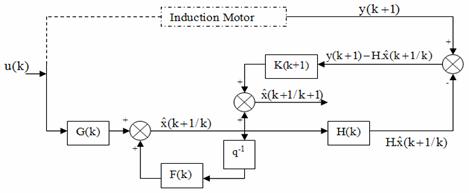
Figure 2. The general diagram of the Extended Kalman Filter
Equations (2.5a)-(2.5b) define a continuous model, but as estimation is to be implemented on a digital processor, the IM continuous model must be written in a discrete form. By applying the Euler formula a discrete time-varying non-linear model is obtained:
|
|
(3.7) |
|
|
(3.8) |
The discrete time varying nonlinear stochastic model of the induction motor has the following form:
|
|
(3.9) |
|
|
(3.10) |
where x(k), u(k) and y(k) are respectively the state vector, the input vector and the output vector which are defined as fellow:
|
|
(3.11) |
|
|
(3.12) |
The process and the measurement noise vectors are random variables and characterized by:
|
|
(3.13) |
|
|
(3.14) |
The initial state x(0) is characterized by:
|
|
(3.15) |
MRAS Based Rotor Speed Estimation
The MRAS technique is used in sensorless IM drives, at a first time, by Schauder [26]. Since this, it has been a topic of many publications [8-9]. The MRAS is important since it leads to relatively easy to implement system with high speed of adaptation for a wide range of applications. The basic scheme of the parallel MRAS configuration is given in figure 3. The scheme consists of two models; reference and adjustable ones and an adaptation mechanism. The block reference model represents the actual system having unknown parameter values. The block adjustable model has the same structure of the reference one, but with adjustable parameters instead of the unknown ones. The block adaptation mechanism estimates the unknown parameter using the error between the reference and the adjustable models and updates the adjustable model with the estimated parameter until satisfactory performance is achieved.
Using a proportional plus integral (PI) observer, the IM speed observer equation is given by (4.1) [27]:
|
|
(4.1) |
This expression depends on the unknown rotor flux components (ψrα and ψrβ). Therefore, these two variables are added to the state vector and estimated using the EKF.
Stability of this observer and convergence of estimation have been proven in several papers [7-9].
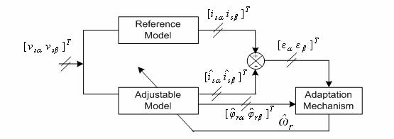
Figure 3. Schema of the rotor speed estimation based on MRAS structure
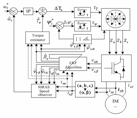
Figure 4. Direct Torque Control bloc diagram of a sensorless IM drives.
Simulation Results
The efficiency of the proposed control scheme has been verified using MATLAB/SIMULINK software package. Motor parameters used in simulations are given in Table 3.
Figure 5. The electromagnetic and load torque.
Figure 6. The stator flux magnitude
Figure 7. Stator flux linkage trajectories during starting and steady state, (a) with compensation of the stator resistance variation effect, (b) without compensation of the stator resistance variation effect.
Figure 8. The actual and estimated stator currents
Figure 9. The actual and estimated stator flux linkages
Figure 10. The actual and estimated speed (a) using the EKF, (b) using the MRAS
Figure 11. The actual and estimated stator resistance, (a) Abrupt variation, (b) Smooth variation
Table 3. Motor Data
|
Rated power |
3 kW |
|
Rated speed |
1440 rpm |
|
frequency |
50 Hz |
|
p |
2 |
|
Rs |
2.3 |
|
Rr |
1.55 |
|
Ls = Lr |
0.261 H |
|
M |
0.249 H |
|
J |
0.0076 kg.m2 |
The ripple affecting both electromagnetic torque response Fig. 5 and flux response Fig. 6 is due to the use of hysteresis controllers.
In Fig. 7 (b) it can be seen the effect of the stator resistance variation due to temperature. After 0.6 s and due to the stator resistance increase, the stator flux linkage trajectory is decreased. By contrast, Fig. 7 (a) shows that the stator flux trajectory is kept constant in presence of stator resistance variation and this is due to the online adaptation of the control algorithm by the observed stator resistance using the EKF.
The real and estimated state variables using the EKF are given respectively in Fig. 8 to Fig. 11. It is clearly shown that the estimated variables are in close agreement with the real ones.
Figure 12. The actual and estimated speed at low speeds range, (a) using the EKF, (b) using the MRAS
Figure 13. Rotor speed estimation errors, (a) using the EKF, (b) using the MRAS
Figure 14. Evolution of the stator flux position
Figure 15. Sectors succession during the IM control using the DTC strategy
Figure 16. The electromagnetic and load torque for varied targets
Discussions
Parameter variation effects
In order to test the sensitivity of the DTC of the IM to the parameter variations, the nominal and the estimated stator resistance are initially set equal, and then at 0.6s the stator resistance is changed to 1.5 times the nominal resistance.
The results are shown in Fig. 11 (a) and (b). Fig. 11 (a) shows the tracking of the stator resistance (for a smooth change). Fig. 11 (b) also shows the tracking of the stator resistance variations. In this last case, the stator resistance value is changed abruptly: stepped-up by 50 % of its initial value. It is clearly shown that the estimated stator resistance converges after less than 1 ms to the nominal value with a tiny error. This result demonstrates that even if the stator resistance changes abruptly, the EKF still gives a good estimate of this major parameter.
Measurement noises effects
To highlight the robustness of the observer, white Gaussian noises with variances of 10-2 are simultaneously added to the measured stator voltages and currents. Fig. 9 shows the real and estimated α and β components of the stator fluxes. The real and estimated rotor speeds are given in Fig. 10 (a) using the EKF and Fig. 10 (b) using MRAS. It clearly appears that the EKF and the MRAS have the property of noises rejection. The on line estimation of the IM states and parameters is tested by many researchers and is proved to give satisfactory results. The most used techniques to estimate these states and parameters are pointed to the EKF.
According to the KF theory, R (measurement error covariance matrix) and Q (process error covariance matrix) have to be obtained by considering the stochastic properties of the corresponding noises [12]. However, since these are usually not known, in most cases, the covariance matrix elements are used as weighting factors or tuning parameters. In this study, tuning the initial values of P and Q is done by trial and error to achieve a rapid initial convergence and the desired transient and steady state behavior of the estimated states and parameters [6].
Steady state and transient behaviors
To compare the performance of the two speed observers EKF and MRAS, it is right to study their behavior at start-up and at steady state regions. Fig. 10 (a) and (b) show respectively, the actual and estimated speeds at starting using the EKF and the MRAS technique. The speed estimation error given by the two observers is negligible, but the error with the MRAS is slightly higher. The estimated rotor speed using the EKF and the MRAS are in close agreement with the real ones.
Operation at low speed region
Since, the MRAS speed estimation used here is based on the proportional plus integral (PI) observer, the well-known pure integration problem at low speed region is encountered in this work. It is concluded that state observation performance of the EKF is quite satisfactory where over all speed region and slightly better than MRAS.
For the investigation of the drive behavior at both low and zero speeds, the reference speed is initially set to 0 rad/s, at 0.4 s it is changed to 20 rad/s, and then at 1.5 s the set point is changed to -20 rad/s. Fig. 12 (a) and (b) show that, the estimated and real speeds are in close agreement with each other in both the forward and reverse directions. The evolution of the stator flux position and the sectors succession during the IM DTC control at low speeds region and under various load conditions are given respectively by Fig. 14 and Fig. 15.
Operation under various load conditions
Unlike the EKF which uses the mechanical equation and requires an accurate knowledge of the load torque for speed estimation, the MRAS observer is derived using the difference between the outputs of two dynamic models, the reference and the adjustable models and the error vector is driven to zero trough an adaptive law.
The load torque impact on the speed estimation is studied under different level of load variations. The reference torque is initially set to 0 Nm, at 0.6 s it is changed to 5 Nm, to the rated value at 1 s and at 1.4 s it is kept again to 0 Nm. Then at 1.6 s the set point is changed to -10 Nm. Fig. 16 shows simultaneously the reference and the electromagnetic torques. Fig. 12 (a) and (b) prove the robustness of the EKF and MRAS to the load torque variations.
Conclusions
In this paper, the well-known classical DTC of IM is detailed and modified to improve its performance, and a comparison between two nonlinear observers, the EKF and the MRAS is presented.
The two observers are studied and compared in the same operating conditions, in order to extract their advantages and drawbacks. Simulation results show that both observers have the property of noise rejection and they are robust against parameters and load variations.
The state observation performance of the EKF is quite satisfactory and slightly better. But, this type of observer requires an accurate knowledge of the load torque and needs more computational time due to heavy matrices manipulations. By contrast, the MRAS strategy doesnt need the load torque to be known and it is much easier to implement.
In a future fellow up work, the proposed scheme is to be implemented on a DSP based on the 16 bits floating point arithmetic Texas Instrument TMS320C31 processor.
References
1. Takahashi I., Noguchi T., A New Quick-Response and High-Efficiency Control Strategy for an Induction Motor. IEEE Trans. Ind. Applicat., 1986, 22(5), p. 820-827.
2. Blaschke F., The Principle of Field Orientation as Applied to the New Transkvector Close-Loop Control System for Rotating-Field Machines. Siemens Review, 1972, l(34), p. 217-220.
3. Mei C. G., Panda S. K., Xu J. X., Lim K. W., Direct Torque Control of Induction Motor-Variable Switching Sectors. IEEE Int. Conf. Power Electron. and Drive Sys., PEDS99, Hong Kong, 1999, p. 80-85.
4. Lascu C., Boldea I., Blaabjerg F., A Modified Direct Torque Control for Induction Motor Sensorless Drive. IEEE Trans. Ind. Applicat., 2000, 36(1), p. 122-130.
5. Aller J. M., Restreo J. A., Bueno A., Paga T., Guzman V. M., Giménez M. I., Sensorless Speed Control of the Induction Machine Combining Field Orientation Method and DTC.
6. Barut M., Bogosyan S., Gokasan M., Speed sensorless direct torque control of IMs with rotor resistance estimation. Int. J. Energy Conv. and Manag., 2005, 46, p. 335-349.
7. Sbita L., Ben Hamed M., An MRASbased full order Luenberger observer for sensorless DRFOC of induction motors. Int. J. ACSE, 2007, 7(1), p. 11-20.
8. Cirrincione M., Pucci M., Sensorless direct torque control of an induction motor by a TLS-based MRAS observer with adaptive integration. Automatica, 2005, 41, p. 1843-1854.
9. Pedro L. R. S., Aurelio G. C., Vicente F. B., Indirect-Field-Oriented Control of an Asynchronous Generator with Rotor-Resistance Adaptation Based on a Reference Model. 15th Triennial World Congress, IFAC, Barcelona, Spain, 2002.
10. Bilal A., Umit O., Aydin E., Mehrded E., A Comparative Study on Non-Linear State Estimators Applied to Sensorless AC Drives: MRAS and Kalman Filter. 30 Annual Conf. of the IEEE Ind. Electron. Society. Busan, Korea, 2004.
11. Ouhrouche M. A., Estimation of speed, rotor flux and rotor resistance in cage induction motor using the EKF-algorithm. Int. J. Power and Energy Sys., 2002, p. 1-20.
12. Messaoudi M., Sbita L., Abdelkrim M. N., On-line rotor resistance estimation for sensorless indirect vector control of induction motor drives. IEEE Forth Int. Multi-Conf. on Systems, Signals and Devices SSD07, El Hammamet, Tunisia, 2007, 2.
13. Kyo B. L., Frede B., Reduced-Order Extended Luenberger Observer Based Sensorless Vector Control Driven by Matrix Converter With Nonlinearity Compensation. IEEE Trans. Ind. Electron., 2006, 53(1), p. 66-75.
14. Cheng Z. C., Hai P. L., An Application of Fuzzy-Inference-Based Neural Network in DTC System of Induction Motor. In Proc. First Int. Conf. on Machine Learning and Cybernetics, Beijing, 2002, p. 354-359.
15. Sbita L., Ben Hamed M., Fuzzy controller and ANN speed estimation for induction motor drives. IEEE Forth Int. Multi-Conf. on Systems, Signals and Devices SSD07, El Hammamet, Tunisia, 2007, 2.
16. Mir S., Elbuluk M. E., Zinger, D. S., PI and Fuzzy Estimators for Tuning the Stator Resistance in Direct Torque Control of Induction Machines. IEEE Trans. Power Electron., 1998, 13(2), p. 279-287.
17. Lascu C., Boldea I., Blaabjerg F., Variable-Structure Direct Torque Control - A Class of Fast and Robust Controllers for Induction Machine Drives. IEEE Trans. Ind. Electron., 2004, 51(4).
18. Sang M. K., Woo Y. H., Sung J. K., Design of a new adaptive sliding mode observer for sensorless induction motor drive, Electric. Power Sys. Res., 2004, 70, p. 16-22.
19. Messaoudi M., Sbita L., Abdelkrim M. N., A robust nonlinear observer for states and parameters estimation and on-line adaptation of rotor time constant in sensorless induction motor drives. Int. J. Phys. Sci., 2007, 2(8), p. 217-225.
20. El Hassan I., Westerholt E. V., Roboam X., De Fomel B., Comparison of different state models in Direct Torque Control of induction machines operating without speed sensor. IEEE, 2000, p. 1345-1352.
21. Huai Y., Melnik R. V. N., Thogersen P. B., Computational analysis of temperature rise phenomena in electric induction motors. Applied Thermal Engineering, 2003, (23), p. 779-795.
22. Nick R. N. I., Abdul H. M. Y., Direct Torque Control of Induction Machines with Constant Switching Frequency and Reduced Torque Ripple. IEEE Tran. Ind. Electron., 2004, 51(4), p. 758-767.
23. Faiz J., Sharifian M. B. B., Keyhani A., Proca A. B., Sensorless Direct Torque Control of Induction Motors Used in Electric Vehicle. IEEE Trans. Energy Conv., 2003, 18, p. 1-10.
24. Kang J. K., Sul S. K., New Direct Torque Control of Induction Motor for Minimum Torque Ripple and Constant Switching Frequency. IEEE Trans. Ind. Applicat., 1999, 35(5), p. 1076-1082.
25. José R., Jorge P., César S., Samir K., Hemin M., A Novel Direct Torque Control Scheme for Induction Machines with Space Vector Modulation. 35th Annul IEEE Power Electron. Specialists Conf. Aachen, Germong, 2004, p. 1392-1397.
26. Schauder C., Adaptive Speed Identification for Vector Control of Induction Motors without Rotational Transducers. IEEE Trans. Ind. Applicat., 1992, 28(5), p. 1054-1062.
27. Ben Hamed M, Sbita L.: Speed sensorless indirect stator field oriented control of induction motor based on Luenberger observer, In Proc. IEEE-ISIE Conf. Montréal, Québec, Canada, 2006, 3, p. 2473-2478.