Magnetic Coupled Circuits Modeling of Induction Machines Oriented to Diagnostics
Tarek AROUI, Yassine KOUBAA* and Ahmed TOUMI
Research Unity of Industrial Process Control (UCPI)
National Engineering School of Sfax (ENIS), B.P.: W 3038 Sfax-Tunisia
E-mail(s): tarek.aroui@eniso.rnu.tn, yassine.koubaa@enis.rnu.tn,
Abstract
In this paper, a transient model of the faulty machine is developed. The model is referred to a three phase stator winding, while the rotor has been represented by all the meshes allowing for the representation of various faults. The model is based on coupled magnetic circuit theory by considering that the current in each bar is an independent variable. The model incorporates non-sinusoidal air-gap magneto motive force (MMF) produced by both stator and rotor, therefore it will include all the space harmonics in the machine. Simulations and experimental results were then used to study rotor faults cause-effect relationships in the stator current and the frequency signature.
Keywords
Induction machines; Broken rotor bars and end-rings; Coupled magnetic circuit; Current spectrum.
Introduction
The use of induction motors in todays industry is extensive and the motor can be exposed to different hostile environments, misoperations and manufacturing defects. Internal motor faults ( e.g., short circuit of motor leads, interturn short circuits, ground faults, bearing and gearbox failures, broken rotor bar and cracked rotor end-rings), as well as external motor faults (e.g., phase failure, asymmetry of main supply and mechanical overload), are expected to happen sooner or later [4]. Furthermore, the wide variety of environments and conditions that the motors are exposed to can age, the motor can make it subject to incipient faults. These incipient faults, or gradual deterioration, can lead to motor failure if left undetected.
Early fault detection allows preventative maintenance to be scheduled for machines during scheduled downtime and prevents an extended period of downtime caused by extensive motor failure, improving the overall availability of the motor driven system. With proper system monitoring and fault detection schemes, the costs of maintaining the motors can be greatly reduced, while the availability of these machines can be significantly improved.
Many researchers have focused their attention on incipient fault detection and preventive maintenance in recent years. There are invasive and noninvasive methods for machine fault detection. The noninvasive methods are more preferable than the invasive methods because they are based on easily accessible and inexpensive measurements to diagnose the machine conditions without disintegrating the machine structure.
In order to develop technologies for motor fault detection and diagnosis, it is important to show the proposed theory, schemes, feasibility, and limitations. In the research stage, we require a controllable environment so that we know what types of faults are induced and what types of motor performance are resulted.
The objective of this paper is to develop a model, which is capable to predict the performance of induction machines under rotor failures during transient as well as at steady state.
Induction Machine Modeling
This model follows the coupled magnetic approach by treating the current in each rotor bar as an independent variable. The effect of non-sinusoidal air-gap MMF produced by both the stator and the rotor currents have been incorporated into the model. This is done by use of the winding function approach.
The analysis is based on the following assumptions [9, 11]: Symmetric machine, uniform air-gap, negligible saturation and insulated rotor bar.
The stator comprises of three phase concentric winding. Each of these windings is treated as a separate coil. The cage rotor consists of n bars can be described as n identical and equally spaced rotor loop [1,3,11]. As shown in Figure 1, each loop is formed by two adjacent rotor bars and the connecting portions of the end-rings between them. Hence, the rotor circuit has n+1 independent currents as variables. The n rotor loop currents are coupled to each other and to the stator windings through mutual inductances. The end-ring loop does not couple with the stator windings [7,11], it however couples the rotor currents only through the end leakage inductance and the end-ring resistance.

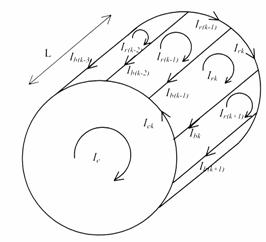
Figure 1. Elementary rotor loops and current definitions
Stator Voltage Equations
The stator equations for the induction machine can be written in vector matrix form as:
![]() (1)
(1)
where
 ;
; ;
;  (2)
(2)
and
![]() (3)
(3)
The matrix [Rs] is a diagonal 3 by 3 matrix which consists of resistances of each coil.
Due to conservation of energy, the matrix [Lss] is a symmetric 3 by 3 matrix. The mutual inductance [Lsr] matrix is an 3 by n matrix comprised of the mutual inductances between the stator coils and the rotor loops.
 (4)
(4)
where Lsrij is the mutual inductance between the stator phase i (i =1, 2 or 3) and the rotor loop j and Lsrie the mutual inductance between the stator phase i (i =1, 2 or 3) and the end-ring.
Rotor Voltage Equations
Given the structural symmetry of the rotor, it is convenient to model the cage as identical magnetically coupled circuits. For simplicity, we assume that each loop is defined by two adjacent rotor bars and the connecting portions of the end-rings between them [1, 10].
For the purpose of analysis, each rotor bar and segment of end-ring is substituted by an equivalent circuit representing the resistive and inductive nature of the cage. Such an equivalent circuit is shown in Figure 2.
From Figure 2, the voltage equations for the rotor loops can be written in vector matrix form as:
![]() (5)
(5)
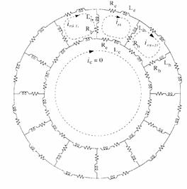
Figure 2. Rotor cage equivalent circuit showing rotor loop currents
and circulating end ring current.
Where
![]() (6)
(6)
In case of a cage rotor, the rotor end ring voltage is Vre=0, and the rotor loop voltages are Vrk=0, k =1,2 n.
The loop equation for kth rotor circuit is:
![]() (7)
(7)
The voltage equation for the end-ring is:
![]() (8)
(8)
where Rb is the rotor bar resistance and Re is the end-ring segment resistance.
Since each loop is assumed to be identical, the equation (7) is valid for every loop. Therefore the resistance matrix [Rr] is a symmetric (n+1) by (n+1) matrix given by:
 (9)
(9)
In relation (5), the rotor flux can be written as:
![]() (10)
(10)
Due of the structural symmetry of the rotor, [Lrr] can be written in matrix form (11), where Lkk is the self inductance of the kth rotor loop, Lb is the rotor bar leakage inductance, Le is the rotor end-ring leakage inductance and Lki is the mutual inductance between two rotor loop.
 (11)
(11)
Calculation of Torque
The mechanical equation of the machine is [7]:
![]() (12)
(12)
where Cem is the electromagnetic torque, Cr is the load torque, J is the inertia of the rotor and Wm is the mechanical speed.
with
![]() (13)
(13)
where q is the angular position of the rotor and p denotes the number of motor pole pairs.
The electromagnetic torque is given by the following equation [11]:
![]() (14)
(14)
Calculation of Inductances
It is apparent that the calculation of all the machine inductances as defined by the inductances matrices in the previous section is the key to the successful simulation of an induction machine.
The model must take into account the geometric construction of the machine and then include the entire space harmonic.
These machine inductances are conveniently calculated by means of winding functions. This method assumes no symmetry in the placement of any motor coil in the slots. According to winding function theory, the mutual inductance between two windings i and j in any electric machine can be computed by the following equation [6, 10, 12]:
 (15)
(15)
where m0 = 4π.10-7 H/m, g is the air gap, q is the angular rotor position, r is the average radius of the air gap, l is the active length of the motor, j is a particular point along the air gap and εi(θ,φ) is called the winding function and represents the magneto motive force (MMF) distribution along the air gap for a unit current flowing in winding i.
For simulation purposes a three phase, 4Kw, 50hz, 4 pole, 380/220V squirrel-cage induction motor will be treated in this paper. The machine has a stator comprises of three phase concentric winding with 36 slots, 28 rotor bars and two coils per phase. Figure4 shows the MMF distribution produced by 1A of current through the stator phase ²1². Note that both stator phases, ²2² and ²3², produce a similar MMF distribution but shifted by p/3 and 2p/3.
 |
Figure 4. MMF distribution of the stator phase ²1²

Figure 5. MMF distribution of the rotor loop ²1²

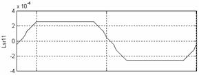
Figure 6.Mutual inductance between the stator phase²1²and rotor loop²1²
The MMF distribution produced by 1A of current through a
rotor loop can only take two values depending on whether we are inside or
outside the loop. The angle between two adjacent rotor bars is ![]() , the MMF
distribution produced by 1A of current through the first rotor loop, is shown
in Figure 5.
, the MMF
distribution produced by 1A of current through the first rotor loop, is shown
in Figure 5.
The mutual inductance between stator and rotor branches will be a function of the rotor position angle q. Figure 6 gives the mutual inductance (Lsr11(q)) between the stator phase ²1² and the rotor loop ²1². Note that the mutual inductance between the phase ²2² and the rotor loop ²1² is Lsr11(q) but shifted to the right by 6g where g is the angle between two stator slots. Mutual inductance between the phase ²1² and the rotor loop ²2² is Lsr11(q) but shifted to the left by a where a is the angle between two rotor bars.
Simulation Results
To validate the proposed model, a functional schema of the induction machine was developed on the Matlab-Simulink platform.
Figure 7 Shows the instantaneous electromagnetic torque, speed, rotor bar current and the phase current of the machine during a start up with a balanced sinusoidal voltage supply followed by the application of a load (Cr = 11Nm) at instant t=0.8s.
Modelling Rotor Bars and End-Ring Faults
Rotor fault have been simulated by including proper relationships between the rotors current variables and reducing the coupling inductance matrix. If the bar between loop k and loop (k+1) is an open circuited, then we require Irk = Ir(k+1) which means that the current is Irk flowing in a double width loop as shown in Figure 8.
This condition is impressed on the inductance matrix [Lrr] by adding the column relating to Irk, meaning the column k to that relating to Ir(k+1) which is the column k+1. The same relationship is applied to the corresponding rows. Similar measures are taken for the resistance matrix [Rr]. The same process is done on the column of mutual inductance [Lsr].
Further open circuited bars are incorporated by repeating the above mentioned reduction process, as required [1].

Figure 7.Torque, speed, rotor currents and stator current in phase ²1²(top to bottom). Normal machine
For the broken end-ring in the section of the kth rotor loop the corresponding loop current is zero as is presented in Figure 9. This situation occurs when Irk = Ire [1].
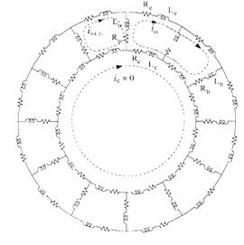
Figure 8. Representation of broken bar
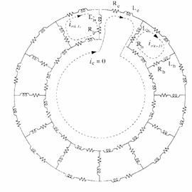
Figure 9. Representation of broken end-ring
Simulation Results
Figure 10 Shows the instantaneous electromagnetic torque, speed and the phase current of the machine with four broken rotor bars and one end-ring, during a start up with a balanced sinusoidal voltage supply followed by the application of a load (Cr = 11Nm) at instant t=0.8s.

Figure 10. Torque, speed, rotor currents and stator current in phase²1²(top to bottom). Machine with four broken rotor bars and one end-ring
We can easly see that the effect of four broken rotor bars and one end-ring is very important. (e.g., the acceleration time under rotor asymmetry is larger than under healthy machine).
Analysis of Steady State Operation
The stator current signal at steady state for the loaded machine is transformed by the Fast Fourier Transform (FFT) into signal in the frequency domain to generate the power spectral density (PSD). The spectrum generated by this transformation includes only the magnitude information about each frequency component, which can be analyzed and processed easier than signal in the time domain.
Spectrum Analysis in the Bandwidth [25Hz-75Hz]
Figure11. Simulated stator current spectrum for healthy machine and for the case of four broken rotor bars and one end-ring (top to bottom)
Figure 11 reports stator current spectrum around fundamental for a normal machine and a machine with four broken bars and one broken end-ring. We can see that rotor anomalies induce some harmonic components, given by [1,8]:
![]() ,k = 1, 2, 3,
(16)
,k = 1, 2, 3,
(16)
Spectrum Analysis in the Bandwidth [100Hz-1000Hz]
There are other spectral components that can be observed in the stator line current due to broken rotor bar fault. The equation describing these frequency components is given by Benbouzid [2] and Nandy [8]
 (17)
(17)
where, ![]() are detectable
broken bar frequencies;
are detectable
broken bar frequencies; ![]() =3, 5,7,9,11,13,
..
=3, 5,7,9,11,13,
..
Figure 12 shows the simulated plot of the stator
currents spectrum affected by the frequency components![]() around 5th and 7th
time harmonic with rotor failures.
around 5th and 7th
time harmonic with rotor failures.
By analyzing a zoom around the 5th time harmonic (Figure
13), we can visualize the presence of the principal components![]() . We notice
the presence of additional frequency components which are spaced by 2sfs.
This can be verified on space harmonic 7, 11, 13
. We notice
the presence of additional frequency components which are spaced by 2sfs.
This can be verified on space harmonic 7, 11, 13
Then, it is necessary to complete equation (17) to take into consideration these harmonics because they are indicative of failure presence in the rotor cage. The new equation will be:
 (18)
(18)
where, fhbc is detectable
broken bar frequencies; ![]() =3,5,7,9,11,13,
.. And b = 0,1,2,3,
=3,5,7,9,11,13,
.. And b = 0,1,2,3,
Figure12. Simulated stator current spectrum for faulty machine around the 5th and 7th time harmonic
2sfs
![]()
![]()
Figure13. Simulated stator current spectrum for faulty machine around the 5th time harmonic
Experimental Setup and Results
The characteristics of the 3 phase induction motor used in our experiment are listed in Table1. The needed load of the induction motor was established by connecting the test motor to an eddy current brake via a flexible coupling (Figure14). In order to allow tests to be performed at different load levels, the brake DC supply current is controllable.
A current Hall Effect sensor was placed in one of the line current cables. The stator current was sampled with a 4 KHz rate and interfaced to a pentium PC by an ARCOM acquisition board.
The motor was tested with the healthy rotor and a faulty rotor with two broken bars. The bars were broken by drilling holes through them.
Table 1. Induction motor Characteristics used in the experiment
|
Description |
Value |
|
Power |
5.5 kW |
|
Input Voltage |
220/380 V |
|
Full load current |
20.6/11.9A |
|
Supply frequency |
50 Hz |
|
Number of poles |
2 |
|
Number of rotor slots |
28 |
|
Number of stator slots |
36 |
|
Full load speed |
2875 rpm |
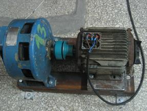
Figure 14. View of the experimental setup
As predicted by simulation, Figure15 and Figure16 show the experimental results with healthy and faulty machine around fundamental. We can see the amplitude of the sidebands components fbc according to equation (16) in the faulty machine current increase over their counterpart in the case of the healthy machine.
Experimental results show significant changes around the 5th time harmonic (Figure17). According to equation (18), space harmonic spaced by 2sfs can be clearly seen.
Figure15. Experimental plots of stator current spectrum around fundamental of the healthy machine
Figure16. Experimental plots of stator current spectrum around fundamental of the faulty machine with two broken bars
2sfs
![]()
![]()
Figure17. Experimental plots of stator current spectrum around 5th time harmonic of the faulty machine with two broken bars
Conclusion
A detailed model of a squirrel-cage induction machine has been developed. In order to simulate incipient broken rotor bar and end-ring fault, the machine was modeled as a group of coupled magnetic circuits by considering the current in each rotor bar as an independent variable. The model can simulate the performance of induction machines during transient as well as at steady state, including the effect of rotor faults. Simulation and experimental results were then used to identify low and high frequency spectral components created by rotor anomalies in the stator current spectrum.
Acknowledgement
The authors would like to thank SITEX Company who finances this work. They also wish to express their deep appreciation for the support rendered by the electrical department members
References
1. Ah-Jaco A., Modélisation des moteurs asynchrones triphasés en régime Transitoire avec saturation et harmoniques despace. Application au diagnostic, thèse de doctorat de luniversité de Lyon juillet 1997.
2. M.E.H. Benbouzid, A review of induction Motors signature analysis as a medium for faults detection, IEEE Transaction on Industrial Electronics, vol. 47, N° 5, pp 984-993, October 2000.
3. Casimir R. E. Bouteleux, Yahoui H., G. Clerc , Henao H., C. Delmotte, Capolino G.-A., Rostaing G., Rognon J.-P., Foulon E., Loron L., Didier G., Razik H., Houdouin G., Barakat G., Dakyo B., Bachir S., Tnani S., Champenois G., Trigeassou J.C., Devanneaux V., DagueB. and Faucher J., Comparaison de plusieurs méthodes de modélisation et de diagnostic de la machine asynchrone en présence de défauts, Proceedings of EF2003 Electrotechnique du futur, 9 et 10 décembre 2003, Supélec.
4. M. Y. Chow, Methodologies of using neural network and fuzzy logic technologies for motor incipient fault detection, World Scientific Publishing Co. Pte. Ltd, Singapore, 1997.
5. Filippetti F., Franceschini G., Tassoni C. and Vas,P., AI techniques in induction machines diagnosis including the speed ripple effect, IEEE Trans. Indus. Appli. Vol.34, n°1, pp.98-108, 1998.
6. Luo X., Liao Y., Toliyat H.A., El-Antably A. and Lipo T.A., Multiple coupled circuit modeling of induction machines, IEEE Transaction on Industry apllications, vol. 31, N° 2, pp 311-318, March/April 1995.
7. Munoz A.R. and Lipo T.A., Complex vector model of the squirrel-cage induction machine including instantaneous rotor bar currents, IEEE-IAP, vol. 35, N°6, 1999
8. Nandi S. and Toliyat H.A., Condition monitoring and fault diagnosis of electrical machinesA review, in Conf. Rec. IEEE-IAS Annu. Meeting, vol. 1, Phoenix, AZ, pp. 197204. 1999
9. Razik H.and Gaëtan D., Sur la détection dun défaut au rotor des moteurs asynchrones, La revue 3EI n° 27, Décembre 2001
10. Toliyat H.A, Lipo T.A., and White J.C., Analysis of a concentrated winding induction machine for djustable speed drive application part 1 (Motor analysis), IEEE Transaction on Energy Conversion, vol. 6, N° 4, pp 679-684, Dec 1991.
11. Toliyat H.A. and Lipo T.A., Transient analysis of cage induction machines under stator, rotor bar and end-ring faults, IEEE Transaction on Energy Conversion, vol. 10, N° 2, pp 241-247, June 1995.
12. Al-Nuaim N.A. and Toliyat
H.A., A novel method for modeling dynamic air-gap eccentricity in
synchronous machines based on modified winding function theory, IEEE Transaction
on Energy Conversion, vol. 13, N° 2, pp 156-162, June 1998.![]()