Development of a Dual-Mode Laboratory-Sized Pelletizing Machine
Collins N. NWAOKOCHA, Olasunkanmi O. AKINYEMI
Mechanical Engineering Department, Olabisi Onabanjo University, Ago-Iwoye, Nigeria
E-mail(s): colneks2000@yahoo.com, sukiyomakie@yahoo.com
Abstract
For research and development work and for the production of small quantities of pellets for specific applications, it is important to have a low-cost apparatus or machine for making pellets. This project work discusses the local design and manufacture of a dual-mode pelleting machine. It can be powered either electrically or manually. It takes care of power failure problems, and can be used in rural settlements where electricity supply is not in existence.
The laboratory-sized pelleting machine uses a worm screw for propelling the grains/mash/mineral ore through the die. The worm screw encased in the pelleting chamber is propelled by a dual mode mechanism i.e. motorized and manual. This worm screw is fed by a hopper, which is able to hold a large quantity of mash/mineral ore at a time.
Many engineering machine are mostly sourced abroad, thereby reducing the development of technology in Nigeria. It is against this background that the present project is conceived making the project work significant.
Keywords
Hopper, Worm Screw, Pellets, Extrusion.
Introduction
In the recent past, fish and poultry and animals are always feed in a primitive way. This involves grinding of grains and cereals as meals on stones and mortar. However, the animals need nutrients and vitamins in addition to aid their growth and development in order to meet the market requirement.
Due to technological advancement grinding machines were developed for grinding of cereals and grain with the mixture of other nutrients into powder form. With time, it was discovered that the animals preferred feeding on solid and soft nutritious meal. One of the devices that can produce this requirement is called a pelletizing machine. [1]
Pelletizing machines are built to perform the following functions, viz - mould animal feed meals in form of soft capsules, which can easily be consumed by fish and poultry animals; to form saw dust and grass (fuel) pellet used in a pellet stove as fuel; production of iron ore pellets in varying diameters for blast furnace pig iron production; and also production of chemical pellet. [2,3]
Pellets are produced through the process called extrusion. Pelletizing machine comprises of some basic component like the hopper through which the feed meal is feed into the machine, to the pelleting chamber which consists of the worm, auger or screw (shaft) which propel the feeds. The shaft is controlled manually by the handle which could also be motorized. The output pellet is formed by compacting and forcing through a die opening (with suitable diameter die hole) by a mechanical process. [1]
Design Analysis and Calculations
Design Considerations
The general consideration in designing this dual – operational pelletizing machine is to produce a machine that can be easily assembled or disassembled, a machine in which the hopper allows materials to pass through effectively with minimum wastage; the pelleting chamber is made of metal so as to increase its durability; the hopper is sloppy to allow pellets to slide downward and get discharge by gravity.
Hopper Design
A hopper in form of rectangular based pyramid frustum, which is made of mild steel, is considered.
The selected dimensions are:
· Upper face of the hopper: 260mm x 250mm
· Lower face of the hopper: 70mm x 50mm
· Height: 160mm.
The development of the hopper is such that the dimensions are marked out and cut out from a mildsteel sheet, then welded together.
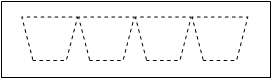
Figure 1: Development of the hopper.
Pelleting Pressure Chamber
The inner diameter d1 = 16mm and the outer diameter d2 = 20mm. The thickness t, to inner diameter ratio is t/d1 = 0.125.
A cylinder with t/d1 < 0.05 is generally regarded as a thin walled cylinder. [4] Thus, this pelleting cylinder is a thick walled cylinder theory, the radial stress σr, the hoop stress σh and the axial stress σz at a diameter d in the body of the cylinder are given as:
 (1)
(1)
 (2)
(2)
![]() (3)
(3)
For open ends of cylinder when an internal pressure P1 is applied only. The minimum stresses occur at the cylinder bore, that is, at d = d1. The internal pressure which is equal to the extrusion pressure is:
P1
= Design extrusion force/Bore area= 10N]/![]() = 0.5 N/mm2
= 0.5 N/mm2
Thus, from equations 2, 3 and 3, the radial stress at the bore is σr = P1 = 0.5N/mm2 and the hoop stress at the bore is σh = 2.28N/mm2.
The maximum octahedral shearing stress criterion of failure is used for the design. [4] This criterion is given as:
![]() (4)
(4)
where Y is the yield stress of the material. Thus, substituting σr = 0.5N/mm2, σh = 2.28N/mm2 and σz = 0 into equation 5, we have Y = 1.47N/mm2 which is less than the yield stress of mild steel (Y = 280N/mm2). [5] Therefore chamber design is okay.
Worm Screw
The worm screw specified has a pitch diameter, Dp = 27mm, and thread pitch pt = 10mm. In designing for thread wear the following formula is used. [5]
![]() (5)
(5)
where
P = force acting along the screw
Perm. = permissible mean nut pressure.
Ø=H/dp = 1.2 to 2.5 for unsplit nuts and H = nut thickness.
We select Ø= 2 and Perm = 0.80KN/cm2 (for steel screw, cast iron nut).
For P = 10N, from equation 6,
Dp = 19.9mm
which is less than the specified pitch diameter of 27mm. Hence, worm screw design is okay.
Motor (Power Requirement)
Once the palletize size is determined, it is necessary to select the drive size. The drive is connected to a gear reduction system, which decreases the drive output and increases the torque to a satisfactory level.
A simplified analysis illustrates the interaction of various parameters that determine the power requirements in a meter section containing the material. Material is considered sheared between a rotating screw and a stationary shaft. Applying laws of physics and rearranging elements of equations to establish necessary power and energy relationships. [6]
Work = force x distance
Power =work/time
Power =Force´distance/time
Power = Force´Velocity
= Force´Screw Circumference ´ rpm
= P´pDN/60
Substituting for P = 10N (design force), D = 16mm (0.016m) and N = 40rpm. The theoretical power requirement is given as:
P
= 10´![]()
= 0.335 Watts
This is less than the gear reducer size selected, which is 0.5horsepower (0.5HP).the excess capacity of the gear reducer over the maximum horsepower available is the service factor. This provide good service life.
Construction & Performance Evaluation
Main features
The main features of the machine are: the hopper, pelleting chamber, worm screw, die, bearings, and the power transmission unit. The assembled machine is shown in Figure 2.
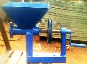
Figure 2: A Dual-Mode Pelletizing Machine
Operating Principle
The material to be pelletized is poured into the funnel/hopper of the machine. Due to gravitational action the feed goes into the pelletizing chamber. The handle/motor is used to move or rotate the screw/auger in the cylinder, the feed experiences circular orbit in a horizontal plane about the axis.
With the help of the shaft and cylinder, the force on the cylinder impacts the feed into solid, which is pushed to the die. The movement of the feed with the force against the die causes pellets of uniform size, shape and density to come out through the holes on the die.
Performance Test
Two tests were conducted on the pellets produced by the pelletizing machine. Both tests were conducted with 1kg of livestock feedmeal. The tests are carried out for each of the manually operated and electrically powered operations-
A.
Pelleting efficiency, ηp = ![]()
Where wr = Total weight recovered.
wT = Total weight fed in.
B. Pellet strength (green) vis-à-vis varying percentage moisture content.
The test facility to determine the green strength of pellet produced was not in our disposal. But from the operation performed during the test on pelleting efficiency, it can deduced qualitatively that increase in moisture content reduces the strength of the pellet thus the pelleting process is slow.
Discussion
The fabricated pelletizing machine can be operated both manually as well as by electric power. It is therefore versatile and simple. The total cost of production of a unit is estimated to be about N= 22,000.00 including both manufacturing and overhead costs. This is affordable for an average entrepreneur.
The performance tests conducted indicated that high values of pelleting efficiency are attainable when powered electrically and manually operated.
Both tests were conducted with 1kg of livestock feedmeal. When manually operated, the pelleting efficiency was found to be 91.4%. That of electrically operated machine gave the efficiency of 92.6%. These levels of performances are satisfactory. For the green strength. a moisture content that supports good pellet formation must be used.
Conclusions and Recommendation
The constructed pelletizing machine has been found to be effective and efficient. It can be powered both electrically and manually. Therefore, it can be used by both rural as well as urban dwellers. It is also affordable since the cost of production is low.
Efforts should be made to adopt and popularize this design, especially for the benefits of rural people who make up a greater percentage of the nation’s population. It is also hoped that when mass-produced, the unit cost would even be lower than it is now.
Acknowledgement
The Authors expresses their gratitude to Mr. Moses for fabricating and assisting in testing the machine.
References
1. Pellets. www.wikipedia.org.
2. Extrusion. www.wikipedia.org.
3. Iron pellets. www.wikipedia.com.
4. Ryder, G. A., (1977) Strength of Materials, The Macmillan Press Ltd., London.
5. Doboronolsky, V; Zablonsky, K; Mak, S; Raddik, A; and Etlikh, L; (1977), Machine Elements, MIR Publisher, Moscow.
6. Akinyemi, O. O; (2002), Production and Performance Evaluation of an Electrode Coating Machine. MSc thesis submitted to the Department of Industrial and Production Engineering, University of Ibadan, Ibadan.
Nomenclatures and Symbols
B = Hopper’s breath
H = Hopper’s height
L = Hopper’s length.
A = Area of base
P = Power
Dp = Pitch diameter
Y = Yield stress
![]() = Maximum Octahedral shearing stress
= Maximum Octahedral shearing stress
t = Thickness
d1 = Inner diameter
d2 = Outer diameter
σr = radial stress
σh = hoop stress
σz = axial stress
M = Mass of the hopper
Mb = Bending moment
R = Radius of cylinder
V = Volume of the hopper
WT = Total weight fed in
Wr = Total weight recovered
ηp = Pelleting efficiency