Experimental Investigation of Characteristics of a Double-Base Swirl Injector in a Liquid Rocket Propellant Engine
1*Fathollah OMMI, 2Koros NEKOFAR, 1Amir KARGAR, and 1Ehsan MOVAHED
1,*Mech.Eng.Dep., Tarbiat Modares University, Tehran, Iran
2Islamic Azad University of Tafresh, Tafresh, Iran
E-mails: *fommi@modares.ac.ir, nekofar@yahoo.com, emovahed@yahoo.com, karegar@yahoo.com
(* Corresponding author)
Abstract
In this work the fundamentals of swirl injector calculation is investigated and new design procedure is proposed. The design method for double-base liquid-liquid injectors is presented based on this theory and experimental results. Then special conditions related to double-based liquid-liquid injectors are studied and the corresponding results are applied in design manipulation. The behaviour of injector in various performing conditions is studied, and the design procedure is presented based on obtained results. A computer code for designing the injector is proposed. Based on this code, four injectors are manufactured. A specialized laboratory was setup for the measurement of macroscopic spray characteristics under different pressure such as homogeneous droplet distribution, spray angle, swirl effect. Finally, through PDA cold test, the microscopic characteristics of injectors spray are also obtained and measured. The results, which will be explained in detail, are satisfactory.
Keywords
Swirl Injector, Double-Base Injector, Macroscopic and Microscopic Characteristics, Atomization, PDA Laboratory
Introduction
The double-based liquid-liquid injectors have many advantages making them applicable in aerospace industries. Fuel and oxidizer can be mixed more efficiently in such injectors, creating an ideal combustion condition and reducing the probability of combustion instability. Since fuel and oxidizer are both exhausted from one injector, without any increase in the diameter of injector plate, a higher discharge rate of fuel and oxidizer can be obtained. In the same way with a fixed discharge rate, it is possible to decrease combustion chamber diameter, and have a stronger thrust. This, in turn, gives higher pressure in the combustion chamber.
The injector has been designed in a way that the fluid may swirl around its axis. The swirl effect's advantages include producing micro-diameter droplets and desirable spray angle, which provide the perfect combustion condition.
In the following design procedure, the governing equations for an ideal fluid are solved and the results are corrected using correction factors based on experimental data. The rules used in the swirl injector theory are based on the principles of mass, angular momentum, energy conservation (Bernoulli's Equation), maximum flow rate and minimum energy laws.
Figure1 shows a schematic of a swirl injector in which dBx, LBx and DK are the entrance whole diameter, the length of entrance hole and the rotation radius, respectively [1].
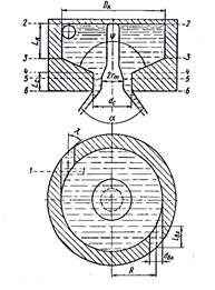
Figure 1. Double base- swirl injector cross section [1]
The geometrical parameter of a swirl injector has an important role in the design procedure and is defined bellow [1]:
![]() (1)
(1)
Where rc is exit hole diameter of nozzle.
According to the conservation of angular momentum principle, parameter M is constant.
![]() (2)
(2)
The swirl force of the fluid increases as it passes through the injector. Due to this force, a hollow cylinder shape flow forms at the exit of the injector, this is filled by air. The cross section area of this flow is equal to:
![]() (3)
(3)
Where, rm, rc and φc are the inner, outer radius of flow and nozzle contraction coefficient respectively. φc is defined as:
![]() (4)
(4)
According to the maximum mass flow rate principle, for an optimal amount of φc the discharge rate of the injector becomes maximum. The injector flow rate is equal to:
![]() (5)
(5)
In which, µ is called discharge rate coefficient which is a function of A and φc. According to the explanations given above and the principal of maximum discharge rate, dμ/dφc=0 and from this, the relationship between A and φc is obtained.
The Friction Effect on the Flow
When the fluid passes through the entrance whole and reaches to swirl chamber, a pressure drop is formed in fluid that is equal to:
![]() (6)
(6)
Where, ζBx is the drop coefficient of entrance hole and is obtained from experimental tests. Figure2 shows the variation diagram of ζBx as a function of Reynolds number, which is defined as the following:
![]() (7)
(7)
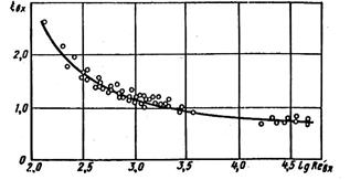
Figure 2. Diagram of the amount of input channel resistance ξBX and Reynolds number Re[1]
When the fluid enters to swirl chamber from entrance hole, it contracts in a way that the average radius of rotation increases and changes from R to Rє. A coefficient named є is defined here and is found from experimental tests as follows:
![]() (8)
(8)
Figure3, presents the variation of є versus 1/B,
where![]() .
Using the coefficient є, the injector geometrical characteristic can be
calculated from:
.
Using the coefficient є, the injector geometrical characteristic can be
calculated from:
![]() (9)
(9)
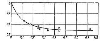
Figure 3. Relationship of amount of transformation input current ε and 1/B
There is a loss of energy inside the swirl chamber due to the friction between the fluid and the wall. The amount of friction is obtained using the friction coefficient גk which is obtained from figure 4. The parameter θ is defined that shows the amount of the friction effects and is equal to [1]:
![]() (10)
(10)
where, Rk is the radius of swirl chamber.
A hydraulic jump occurs because of an abrupt change in flow path slop, just after the nozzle entrance cone. This in turns causes an energy loss in entrance channel (ΔBx), swirl chamber.
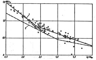
Figure 4. Relationship between value of friction and the input Reynolds number [1]
1) Experimental relation, 2) Theoretical relations
The shape of spray is a cone with an angle, which its calculated value is corrected using the following correction factor:
![]() (11)
(11)
Where αEXP and αт
are experimental and theoretical values of α, respectively. Figure
5 shows the diagram of ![]() versus the θ collection.
versus the θ collection.
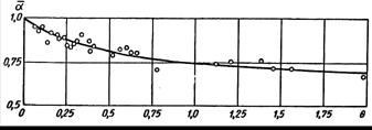
Figure 5. Relationship of spray cone relative angle α with θ set
Swirl Injector Design Procedure
The swirl injector should provide the necessary discharge rate of the fluid under a definite spray cone angle and the pressure difference. It is also recommended to have minimum energy drop, in order to face with minimum reduce of exit flow velocity and injection quality.
As mentioned before the total amount of θ determines
the effect of friction and the smaller value of θ show the smaller effects
of fluid viscosity on the injector hydraulics. For low viscosity liquids such
as gasoline, oil and water, the suitable range of injector expansion coefficient
(![]() )
recommend within 1.25≤Cc≤5. In this state as spray,
cone angle is larger; the size of Cc should be smaller. As
the length of nozzle is not desirable, since it leads to a decrease in the
spray cone angle, it is recommended to take (Lc=Lc/dc)
in the range of
)
recommend within 1.25≤Cc≤5. In this state as spray,
cone angle is larger; the size of Cc should be smaller. As
the length of nozzle is not desirable, since it leads to a decrease in the
spray cone angle, it is recommended to take (Lc=Lc/dc)
in the range of![]() . It is also, recommended to take the
input cone angle to nozzle in the range of
. It is also, recommended to take the
input cone angle to nozzle in the range of ![]() range. If the entry canals do
not have sufficient length, the current fails in taking tangent direction and
inclines towards the rotation chamber axis and as a result, the cone spray
angle becomes smaller and the discharge coefficient becomes bigger. Therefore,
the length of input canals should not be smaller than one and a half time of
its internal diameter. On the other hand, this length should not be too large
since in such situation, the energy loss resulted from friction becomes high.
range. If the entry canals do
not have sufficient length, the current fails in taking tangent direction and
inclines towards the rotation chamber axis and as a result, the cone spray
angle becomes smaller and the discharge coefficient becomes bigger. Therefore,
the length of input canals should not be smaller than one and a half time of
its internal diameter. On the other hand, this length should not be too large
since in such situation, the energy loss resulted from friction becomes high.
In most injectors, 2 to 3 canals will be sufficient to make the symmetric spray cone. When the number of canals becomes more than three, no considerable change is made in the quality of fuel distribution; however, the injector structure becomes more complex and its precision becomes less. In open injectors (low amounts of Cc) the loss of energy reveals itself in input canals; thus, it is necessary to take Cc bigger than 1.25(Cc≥1.25).
The hydraulic design of a simple swirl injector includes determining dimensions of nozzle, swirl chamber and input canals. The initial data consists of the cone angle of spray, discharge rate, pressure difference of injector, and the entrance angle to nozzle, number of holes to the swirl chamber, density and fluid viscosity. The design stages could be described as below:
1. Determine the values of ψ, n, Cc, V, ρ, G, ΔPФ, α and Δ.
2. Considering
α0=0.85 as the first approximation from its range of
variation, ![]() and calculating the spray cone angle
from:
and calculating the spray cone angle
from:
![]() (12)
(12)
3. Obtaining the values of AD1 and α1 using Figure 6.
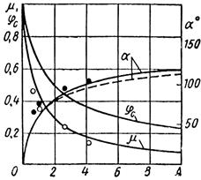
Figure 6. Relationship of discharge coefficient and nozzle contraction coefficient and spray angle to the geometric characteristic of injector [2]
4. Determine the value of μ1 using Figure6.
5. Obtain the injector nozzle diameter from the following equation:
 (13)
(13)
6. Determine the swirl radius Rl, using chosen value of Cc and Rcl.
![]() (14)
(14)
7. Calculating the entrance channel diameter using the following relation:
 (15)
(15)
ε0 = 0.8 as the first approximation.
8. Calculating the flow Reynolds number [4]:
![]() (16)
(16)
9. Determine the friction coefficient using Figure4.
10. Calculate the injector equivalent characteristic length using [5]:
![]() (17)
(17)
where![]() and
and 
11. Obtaining the value of α1 using Figure5.
12. Determine μθ1 and αθ1 using Figure6.
13. Calculate the first approximation of spray cone angle [6]:
![]() (18)
(18)
14. Calculate the total energy loss in injector using Figure2:
![]() (19)
(19)
15- Calculating ΔBXl using the following equation:
![]() (20)
(20)
16. Calculating Δkl by the following equation [7]:
 (21)
(21)
17. Selecting an appropriate value for nozzle resistance coefficient (ξc) in the range of 0.11 and 0.16 [1].
18. Obtaining φc using Figure 6 and considering A= Acl .
19. Calculating ΔCl using the following equation:
![]() (22)
(22)
20. Obtaining a first approximate value for![]() [8]:
[8]:
![]() (23)
(23)
21. Calculating the coefficient of transformation, εl, via Figure3.
22. Updating the values of ε1, μp1 and α1 by comparing the calculated values of ε0, μ1 and α0. If the difference exceeds the permitted quantity, the second approximation is obtained. In this case, with respect to the given amount, the spray cone angle α0 and amount of α1 obtained from the first approximation is obtained to be as α0= α0/ α1.
23. Considering the value of α2 and using Figure6 the values of μ2 and AD2 are calculated.
24. Calculating μ2 using the obtained coefficient of energy loss, by the following expression.
![]() (24)
(24)
25. Calculating the nozzle injector diameter using the following formula:
 (25)
(25)
26. Obtaining the swirl radius by: R2= Ccrc
27. Calculating the inlet channel diameter using the following expression [9]:
 26)
26)
Where, n is determined before and the amount of λk1, Ck1 and ε1 will obtain in the first approximation.
28. Reynolds number is calculated [10]:
![]() (27)
(27)
29. The friction coefficient is determined using Figure5.
30. Obtaining the injector equivalent characteristic using:
![]() (28)
(28)
Where![]() and
and ![]()
31. Determining the amounts of μθ2 and αθ2 using Figure 6.
32. Obtaining the value of α2 by using Figure5.
33. By
using formula![]() , the magnitude of the spray cone angle
in second approximation is obtained.
, the magnitude of the spray cone angle
in second approximation is obtained.
34. Calculating the energy loss coefficient using the same procedure in the first stage.
35. The discharge coefficient in second approximation is obtained from following relations:
![]() (29)
(29)
36. Obtaining the value of ε2 using the values of B2 and ε1 (Figure3).
37. Comparing the calculated values of ε2, αp2 and μp2 with the previous values of ε1, α0 and μp1 in order to calculate their approximation. If a good convergence cannot be obtained, a smaller value for cc should be selected and the appropriate stages have to repeat.
38. After calculation of dc, R and dBx, other geometrical sizes of injector are calculated. The diameter of swirl enclosure is obtained in the next step by using this formula [11]:
![]()
Then the nozzle length (Lc), inlet channel length (LBX) and swirl enclosure length (Lk) are selected, considering the aforementioned comments.
39. The proposed procedure has an extensive application and its results are precise within ±10%.
The Double-Base Swirl Injector Calculation Results
Figure7 shows a double-base injector. In this injector, fuel and oxidizer are mixed outside the nozzle. The injector parameters should be selected in a way that the fuel and oxidizer spray cones do not cut each other near nozzle outlet. αf and α0 show the spray angle of fuel and the angle of oxidizer, respectively. The design procedure of single injector is applied for designing the double-base injector. An important point in designing this type of injector is that the gas vortex radius of the outer injector should be more than external radius of central injector nozzle. One should also consider that for the contact of two-spray umbrella, the spray cone angle in the inner injector should be more than outer one.
Figure 7. Double-base external mixing injector [2]
Considering an ideal fluid and same pressure difference for fuel and oxidizer paths, the following expressions are derived for these types of injectors:
 (30)
(30)
in
which, ![]() ,
,
![]() are
oxidizer and fuel densities, respectively.
are
oxidizer and fuel densities, respectively.
The oxidizer to fuel mass flow rate ratio is:
 (31)
(31)
Where, mФ0 and mФF are the oxidizer and fuel mass flow rates, respectively. The total flow rate is equal to:
mf=mf0+mfF=![]() (32)
(32)
in
which ![]() .
Considering the law of angular momentum conservation one may write:
.
Considering the law of angular momentum conservation one may write:
![]() (33)
(33)
 (34)
(34)
 (35)
(35)
According to the aforementioned relations, the geometric characteristic of a double-based swirl injector could be written as:
 (36)
(36)
Expression for μФ, φ and α are the same as those for single-base injector with substitution of Ā by A. Therefore, one may write:
![]() (37)
(37)
in
which ![]() and
mf is the
passage efficiency or total discharge rate coefficient and FCФ
is the cross section area of flux in nozzle.
and
mf is the
passage efficiency or total discharge rate coefficient and FCФ
is the cross section area of flux in nozzle.
Depending on the value of![]() , some corrections in
discharge coefficient might be necessary. The relationship between experimental
and theoretical discharge rate coefficient (μФ &
μФEXP) as a function of
, some corrections in
discharge coefficient might be necessary. The relationship between experimental
and theoretical discharge rate coefficient (μФ &
μФEXP) as a function of ![]() is
presented graphically in Figure8 [15].
is
presented graphically in Figure8 [15].
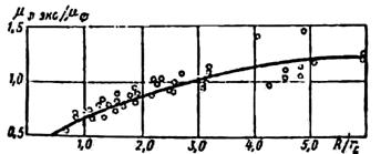
Figure 8. Correction factor of coefficient flow versus swirl radius
Based on the presented design procedure, a computer code is developed, which performs the design and necessary calculations of different dimensions of injector. This program designs injector based on design data and calculates its dimensions. To design a double-base injector, the data of internal and external nozzle should be input in the program separately to obtain its geometry. However, as mentioned, the radius of external nozzle should be more than the external radius of nozzle in the inner injector. At the same time, the spray cone angle of inner injector should be more than outer injector, therefore both spray cones would contact to each other after discharging form injector. According to the design condition, the internal nozzle must inject flow of 20cc/sec in defined pressure of 10 bars. The external nozzle must also inject 120cc/sec in four bars. The spray angles for the internal and external nozzles obtained 85° and 75° respectively.
Manufacturing the Injectors
Four injectors are manufactured based on design calculations. The double-based swirl injector has three parts including internal nozzle, external nozzle and lid. Brass metal was chosen due to its special characteristics for accurate machining and minute drilling. Detailed drawings of internal and external nozzle are shown in figure 9&10. These three parts are brazed and assembled precisely as shown in figure 11.
Figure 9. Manufacturing Diagram of the Internal Nozzle
Figure 10. Manufacturing Diagram External Nozzle
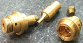
Figure 11. Assembled and disassembled of a Manufactured Injector
Hydrodynamic Test Laboratory
To check the quality of the manufactured injectors, a preliminary laboratory set-up is needed. This set-up will measure the macroscopic characteristics of injectors spray such as homogeneous spray distribution, spray angle and swirl effect on the spray formation under different pressure. This test rig was set up with the following parts as, Injector Stand, Pressurized Liquid Tanks, High Pressure Nitrogen Capsule, Manometer and Regulator, Radial and Sectional Collector, Stroboscope and High Speed Camera. The liquid emitted by the injectors are collected in two different collectors made of flexi glass material as shown in figures 12&13. The level of fluid in the radial and sectional collectors display spray distribution quality in r and θ direction respectively. Sectional collector divided into six 60° section and the radial one divided into three co-centric cylinders. Furthermore, a high-speed camera is used to capture the spray cone angle and atomized spray distribution of both internal and external nozzle.
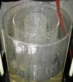
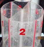
Figure 12, 13. Radial (Left) and Angular (right) Collector
Test Results of Injectors
Flow-Pressure Test
This test is conducted to measure the flow changes under different working pressure for both internal and external nozzle. Figures 14&15 present the results of the experimental flow for a specific set of design conditions.
Figure 14. Flow rate of internal nozzle (cc/s) versus pressure (bar)
Figure15. Flow rate of external nozzle (cc/sec) versus pressure (bar)
Spray Angle Test
To show the spray formation of internal and external nozzle clearly a stroboscope and a high-speed camera are used. Figure 16 displays the spray circulation of injector. As fluid pressure increases from zero to ten bars, the spray cone gradually opens to become fully developed as seen in figure17.
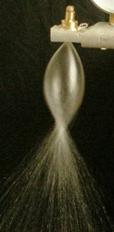
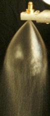
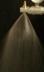
Figure 16. Spray Formation Stages with Regarding to Fluid Swirl
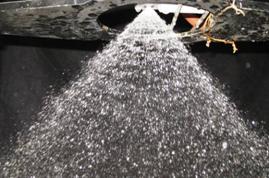
Figure 17. Fully Opened Spray Cone Under design condition (Pf=10, Po=4 bar)
In figures 18 and 19 the spray cone angle of both internal and external nozzle are approximately 70° and 80° respectively under design condition (Po=4, Pf=10 bar) which are satisfactory in the light of theoretical calculations.
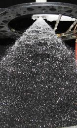
Figure 18. Spray cone angle of internal nozzle
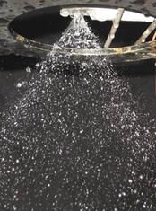
Figure 19. Spray cone angle of external nozzle
Spray symmetry and homogeneity test
Sectional and radial collectors are used to check the symmetry of the fluid spray. To obtain a symmetrical distribution of injection, the machining and drilling processes must be precise and accurate. Figures 20 and 21, shows the spray distribution in each compartment of the collector.
Figure 20. Spray distribution of the injector in each 60° section
Figure 21. Spray distribution of the injector in each cylinder
Microscopic Spray Droplet Test
Using PDPA laser laboratory, the microscopic characteristics of the injector spray have been identified. This instrument works with Doppler frequency difference phenomenon. As shown in figure 22 phase Doppler particle analyzing system consists of a laser light source, optical arrangements, a transmitter, and a data acquisition system. The visualization system used in this experiment consists of a laser source, lenses and mirrors, a high-pressure spray chamber, and CCD camera.
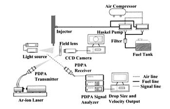
Figure 22. Phase Doppler analysis system
According to figure 23 mounting the injector on the apparatus and setting the fluid tanks pressure on the design condition droplet normal velocity (m/s) and SMD (Micron) distribution at 100mm downstream, for Po=4 and Pf=10 bar and T=25°C, is shown in Figures 24&25 respectively. There is a high velocity zone around the injector axis that represents existence of the spray liquid sheet as it is seen in Figure24. Droplets normal velocities are obtained in the range of 11m/s. According the figure 25, droplets with less mean diameter are placed in center of the spray cone and the diameter increases along radius.
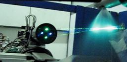
Figure 23. View of laser beams emitted to the spray
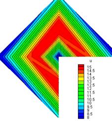
Figure 24. Velocity (m/s) distribution of Spray in a normal plan
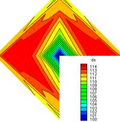
Figure 25. SMD (Micron) distribution of Spray in a normal plan
Conclusion
A theoretical design procedure for double-base liquid-liquid swirl injectors is described. A computer code is developed for the proposed method and the results are compared with experimental data. According to design calculations, four swirl injectors have been manufactured precisely. To check the quality of the injectors, a preliminary laboratory was set up to measure the macroscopic characteristics of sprays such as spray angle, distribution quality. In order to obtain microscopic characteristics such as droplets velocities and SMD PDA laser laboratory was used. Experimental results show that the manufactured injectors based on the design procedure are flawless.
References
1. Ditiakin, E.F., Koliachko, L.F., Noikov, B.V., Yagodkin, V.E., "Fluids Spray", Moscow, 1977.
2. Vasiliov, A.P., Koderaftsov, B.M., Korbatinkov, B.D., Ablintsky, A.M., Polyayov, B.M. Palvian, B.Y., "Principles of Theory and Calculations of Liquid Fuel Jet", Moscow, 1993.
3. Rammurthi, K., Tharakan, J., "Experimental Study of Liquid Sheets Formed in Coaxial Swirl Injectors", J. of Propulsion and Power, VOL.11, №6, 1995.
4. Sivakumar, D., Raghunandan, B.N., "Jet Interaction in Liquid-Liquid Coaxial Injectors", J. of Fluid engineering, VOL.118, June 1996.
5. Sutton, G. P., "Rocket Propulsion Elements", John Wiley & Sons, Fifth Ed, 1986.
6. Huzel, D.K., Huang, D.H., "Design of Liquid Propellant Rocket Engineering", NASA, Second Ed, 1971.
7. Barrerf, M., "Rocket Propulsion", Paris, 1959
8. Chuech, S.G., "Numerical Simulation of No swirling and Swirli3ng Annular Liquid Jets", AIAA J., VOL 31, №6, June 1993.
9. Shames, E. Herman, "Mechanics of Fluids", fourth Printing 1988, McGraw-Hill.
10. Bazarov, V.G., Yang, V., "Liquid-Propellant Rocket Engine Injector Dynamics", J. of Propulsion and Power, VOL. 14, №5, 1998.
11. Jeng, S.m., Jog, M.A., Benjamin M.A., "Computational and Experimental Study of Liquid Sheet Emanationg from Simplex Fuel Nozzel", ALAA Journal, Vol. 36, №2, 1998.
12. Parlange, J.Y., "A Theory of Water-Bells", J. of Fluid Mechanics, VOL. 29, Part 2, 1967.
13. Ghafourian, A., Mahalingam, S., Dindi, H., Daily, J.W., "A Review of Atomization in Liquid Rocket Engines", AIAA Paper 91-0283.
14. Sankar, S.V., Wang, G., Rudoff, R.C., Isakovic, A., Bachalo W.D., "Characterization of Coaxial Rocket Injector Sprays Under High Pressure Environments", ATTA Paper, 1991.
15. Fischer, U., Valinejad, A., "Tables and Standards of Design and Machinery", Taban, Iran, 2005.