Modification and Performance Evaluation of a Low Cost Electro-Mechanically Operated Creep Testing Machine
John J. MOMOH*, Lanre Y. SHUAIB-BABATA and Gabriel O. ADELEGAN
Department of Mechanical Engineering, Federal Polytechnic, Ado-Ekiti
*E-mail: jjmomoh@gmail.com
(* Corresponding author)
Abstract
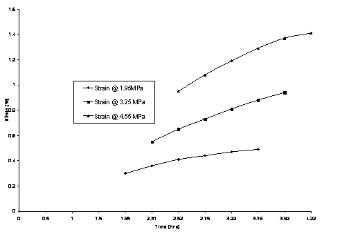
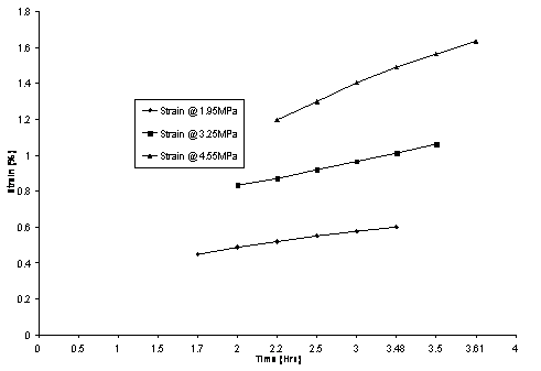
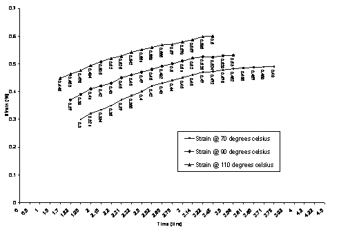
Existing mechanically operated tensile and creep testing machine was modified to a low cost, electro-mechanically operated creep testing machine capable of determining the creep properties of aluminum, lead and thermoplastic materials as a function of applied stress, time and temperature. The modification of the testing machine was necessitated by having an electro-mechanically operated creep testing machine as a demonstration model ideal for use and laboratory demonstrations, which will provide an economical means of performing standard creep experiments. The experimental result is a more comprehensive understanding of the laboratory experience, as the technology behind the creep testing machine, the test methodology and the response of materials loaded during experiment are explored. The machine provides a low cost solution for Mechanics of Materials laboratories interested in creep testing experiment and demonstration but not capable of funding the acquisition of commercially available creep testing machines. Creep curves of strain versus time on a thermoplastic material were plotted at a stress level of 1.95MPa, 3.25MPa and 4.55MPa and temperature of 20oC, 40oC and 60oC respectively. The machine is satisfactory since it is always ready for operation at any given time.
Keywords
Creep; Time; Temperature; Thermoplastic; Testing; Material.
Introduction
Success in todays market place requires improvements in efficiency, quality and accuracy of testing facilities and testing equipment. Testing is an essential part of any engineering activity, it is necessary at any point in the engineering process [1]. Iron, steel, aluminum, copper, lead and zinc and their alloys are metals that are mostly used for the production of appliances, devices, machines and buildings. Recent developments associated with the innovative use of thermoplastics in structural applications demand accurate engineering data. More specifically, the assessment of structural performance requires data that spans appropriate ranges of stress, time, temperature, and strain rate [2]. The spectrum of their properties determines the essential demands on testing machines. Creep testing machines are predominantly used to measure how a given material will perform under constant load, at elevated temperature. The primary use of the creep testing machine is to enable students generate values for creep-time curve. Once the curve is generated, a graph book, pencil and straight edge or computer algorithm can be used to calculate the steady state creep rate for each combination of load and temperature, plot the creep rupture data as the logarithm of stress versus the logarithm of rupture lifetime at constant temperature called stress-rupture-curve.
Creep is define as a time-dependent deformation that happens when metals or other materials are subjected to constant load at high temperature over a period of time [3]. The temperature at which material starts to creep depends on its melting point. Creep at room temperature is more common in polymeric materials and is called cold flow or deformation under load [4]. Soft metals (e.g. lead) creep at room temperature. Thus Andrade commenced studies of creep behaviour in 1910 using lead, since this metal exhibits creep at room temperature [5]. It has been found that plastic deformation at both room and elevated temperatures prior to creep testing has either beneficial or detrimental effect on the materials. As observed by Xia and Ellyin [6], a problem on plastic deformation has been previously studied experimentally for several materials.
Many mechanical systems and components like steam boilers and reactors, steam generators or turbine rotors must operate at high temperature under significant stress. For this reason, the components and structures need to be designed on the basis that excessive creep distortion must not occur within the expected operating life of the plant [8]. Knowledge of the creep behaviour of metals or any material is therefore important.
The importance of mechanical testing of material to students and engineering practitioners cannot be underrated. Most institutions and research institutes in Nigeria face the problem as regards material testing such as, unavailability, ageing, financial constraint in procurement of new machine, etc.
Unavailability of material testing machines such as creep testing machine is the order of the day in most Nigerian schools and research centers. The major source of obtaining these machines is from the foreign based companies. This makes the testing machines to be unavailable. In some cases where they are found, they are either obsolete or non-functioning. Thus the students and professionals rarely get access to testing machine for experimental use.
The present work will proffer solutions to all the factors hindering the accessibility of students and professionals to creep testing machine, since the machine is locally made, ease to procure, maintain, use and affordable due to low cost of production.
Material and Method
The creep testing machine shown in Fig. 1 consists of important features, which must exist in any creep testing machine. These features are:
§ Load Application System
This comprises a load hanger, dead weight and load beam with a mechanical advantage of 8:1. The load beam gives a steady and uniform tensile load. It is a mechanism for applying a load to the test-piece and for carrying the load at a controlled rate.
§ Grips and Fixtures
This is used for locating and holding the test-piece in a satisfactory position. Correct alignment of the grips and the specimen when clamped in the grips is important; offsets in alignment will create bending stresses and lower creep readings. It may even cause the specimen to fracture outside the gage length [8]. The load applied from the hanger through the load beam is transmitted to the material through the upper test piece. The test piece grip is made out of a long steel shaft with a gripping device for threaded-end specimens attached to the top and bottom heads of the machine.
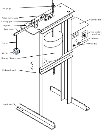
Figure 1. Creep testing machine
§ Strain measuring system
The main mechanism for accurate measurement and recording of change in specimen dimensions is a dial gauge. When a force is applied to the specimen, strain occurs and relative movement between the gripping points is transmitted through the load beam to the dial gauge. The dial gauge is calibrated in steps equivalent to an extension of 0.001mm and the maximum amount of extension measured is 2.5mm.
§ Heating chamber
It is an enclosure to generate and maintain the temperature around the specimen during test. The heating chamber consists of rolled steel iron, refractory and heating element. The refractory is composed of saw-dust, kaolin, ball clay, sodium silicate and silica sand.
§ Test specimen
The standard dealing with the design of test specimen as established by the American Society for Testing and Materials (ASTM) shown in Fig. 2 and Table 1 was in the development of mass production of the specimen using the ETF mini Computer Numerical Control (CNC) turning machine.
Table 1. Standard threaded-end specimen dimensions, mm (ASTM, 2004).
|
G - D - R - A - L - B - C - |
Gage length Diameter Radius of fillet Length of reduced section Overall length Length of end section Diameter of end section |
62.5 ± 0.1 12.5 ± 0.2 10 0.75 145 35 20 |
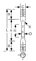
Figure 2. Threaded-end specimen
§ Design of frame
For 6 × 2 U-channel
Area= A m2, Height of frame = L m
Volume = V = A × L = 4.517 × 10⁻³m3
Density of steel = ρ kg/m3
Weight (mass, m) = ρ × V = 35.69kg
1 frame, m= 35.69kg
2 frames, m = 2 × 35.69 = 71.37kg
§ Supporting channels (4 off)
For 5 × 1.75 channels
Volume = V = 0.001298m3
Weight of 1 supporting frame = 10.23kg
4 frames = 40.93kg
L angles bar (unequal legs) 31/2 × 3
Weight of 2 angle bars = 19.43kg
Top plate weight = 22.28kg
Bottom plate weight = 8.295kg
§ Heating chamber
Weight of rolled steel iron + refractory = 74.6kg
Total weight of the frame = Weight of 2 standing channels + weight of 4 supporting channels + weight of 2 angle bars + weight of top and bottom plates + weight of heating chamber = 236.91kg
Since weight of the frame with other accessories is 236.91kg, the applied load should not exceed 23,240.9N
§ Maximum load applied to hanger
From Fig. 3, the weight (W) creates the tensile force
(F) through the simple lever with ![]() = 2905.1N
taking moment about the fulcrum. The maximum allowable load for
the hanger is 2905.1N; any load applied beyond this value will topple the machine.
= 2905.1N
taking moment about the fulcrum. The maximum allowable load for
the hanger is 2905.1N; any load applied beyond this value will topple the machine.
The American Society for Testing and Materials (ASTM) has established a number of standards covering practically every aspect of testing. There are separate standards dealing with the design of the specimens, certifying the testing machine, performing the test, analyzing the results and even comparing the results of tests where different specimen designs were used. These standards are invaluable. They help to ensure that results from many different laboratories are consistent and reliable [9].
§ Test procedure for the testing machine
(i) Remove any load from the hanger
(ii) Measure and write down the specimen cross sectional area A
(iii) Mark out the gauge length (Lo)
(iv) Carefully place the specimen between the lower and upper grips in the furnace
(v) Zero the dial gauge, the lever is locked in place by a locking pin
(vi) The heating element is switched on to heat the chamber to desired temperature
(vii) Apply load gradually and adjust dial gauge to zero.
(viii) At the desired temperature, locking pin is removed and a stop watch is started at the same moment.
(ix) Recordings are taken of extension and time
(x) Recorded values are plotted to produce an extension time graph.
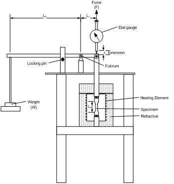
Figure 3. Creep testing machine sectional front elevation.
Results
In order to benchmark the new creep testing machine, several standard measurements and calibrations were made. Creep tests were carried out on Polytetrafluoroethylene (Teflon) for 12.5mm diameter, 62.5mm gage length with creep curve generated as shown in Figures 4, 5 and 6.