Modified Direct Torque Control of Three-Phase Induction Motor Drives with Low Ripple in Flux and Torque
Vinay KUMAR* and Srinivasa RAO
National Institute of Technology, Warangal, A.P., India
E-mails: vinay257@yahoo.co.in, srinivasarao_nitw@yahoo.co.in
*Corresponding author e-mail: vinay257@yahoo.co.in
Received: 11 October 2010 / Accepted 10 March 2011 / Published: 24 June 2011 / Revised: 15 August 2012
Abstract
This paper proposes an algorithm for direct flux and torque controlled three phase induction motor drive systems. This method is based on control of slip speed and decoupled between amplitude and angle of reference stator flux for determining required stator voltage vector. Within the given sampling time, flux as well as torque errors are controlled by stator voltage vector which is evaluated from reference stator flux. The direct torque control is achieved by reference stator flux angle which is generates from instantaneous slip speed angular frequency and stator flux angular frequency. The amplitude of the reference stator flux is kept constant at rated value. This technique gives better performance in three-phase induction motor than conventional technique. Simulation results for 3hp induction motor drive, for both proposed and conventional techniques, are presented and compared. From the results it is found that the stator current, flux linkage and torque ripples are decreased with proposed technique.
Keywords
Direct torque control (DTC); Induction motor drive; Space vector modulation (SVM) technique; Direct stator flux control.
Introduction
Speed control of induction motor drives using direct torque control (DTC) method have become increasingly popular in the industrial drives due to the simplicity in control structure and high dynamic performance of instantaneous electromagnetic torque. Since DTC for induction motor was introduced in 1980s, Field Orientation Control and Direct Torque Control methods are most popular for electric machine vectors control methods [1]. The main disadvantages of Field Orientation Control method is high dynamic performance, switching frequency, low torque ripples and maximum fundamental component of stator current, but field oriented control method suffer severe disadvantages, i.e. requirement of two co-ordinate transformations and current controllers, high machine parameter sensitivity.
Comparing with field-orientated control, DTC has very simple control scheme and also less computational requirements. In case of Direct Torque Control method, current controller and coordinate transformations are not required. The operation of the conventional DTC is very simple but it produce high ripple in torque do to considered non-linear hysteresis controllers. Sampling frequency of conventional DTC is not constant and also only one voltage space vector is applied for the entire sampling period. Hence the motor torque may exceed the upper/lower torque limit even if the error is small [2].
In order to overcome this problem SVM-DTC method was proposed [3]. From the above discussion, the conventional DTC produces high ripple in torque by changing switching frequency. By using space vector modulation technique in DTC, the sampling frequency is maintained constant and reduced torque ripple with low switching losses.
This paper presents the simple and effective algorithm for control of decouple between the amplitude and angle of reference stator flux of induction motor based on a SVM-DTC strategy. The conventional and proposed DTC simulation results are presented and compared. Simulation results show that torque, flux linkage and stator current ripple are decreased with proposed SVM DTC.
Materials and Methods
Machine modelling
By referring to a synchronous reference frame, denoted by the superscript e, the mathematical equations of induction motor can be rewriting as follows [4]:
Stator voltage equation:
|
|
(1) |
Rotor voltage equation:
|
|
(2) |
Stator flux equation:
|
|
(3) |
Rotor flux equation:
|
|
(4) |
Mechanical equation:
|
|
(5) |
|
|
(6) |
Conventional DTC
In a conventional DTC controlled induction motor drive supplied by a three-phase voltage source inverter, main aim is to control directly the stator flux linkage or magnetizing flux linkage or rotor flux linkage and electromagnetic torque by the selection of proper inverter switching states (hysteresis control) [5, 6]. The switching state selection is made to restrict the flux and torque across within respective flux and torque hysteresis bands, to get low inverter switching loss, fast dynamic response and harmonic distortion in stator currents.
The circuit diagram of a conventional DTC is shown in Figure 1.
Direct flux control
From Equation (1) we can write ![]() (stationary
reference frame). If voltage drop in stator resistance is neglected, then the
stator flux linkage vector is given by
(stationary
reference frame). If voltage drop in stator resistance is neglected, then the
stator flux linkage vector is given by ![]() , this equation
is replaced by
, this equation
is replaced by ![]() where
where ![]() is the sampling period.
is the sampling period.
Here, ![]() is the voltage space vector that may
occupy any of the eight space positions as shown in Figure 2. In
is the voltage space vector that may
occupy any of the eight space positions as shown in Figure 2. In ![]() , it is observed
that the stator flux linkage will move fast, if active switching vectors are
applied to voltage source inverter (VSI).
, it is observed
that the stator flux linkage will move fast, if active switching vectors are
applied to voltage source inverter (VSI).
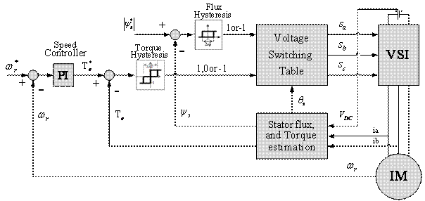
Figure 1. Block diagram of the Conventional DTC
If null switching vectors are applied to VSI, then the stator
flux linkage space vector will stop. For a six-pulse voltage source inverter,
the stator flux linkage space vector traces a hexagonal path with constant
speed. The required flux linkage locus is obtained by applying a switching
sequence of null and active switching vectors shown in Table 1 based on the
location of the flux vector. In this conventional DTC, at every sampling
period, the stator flux linkage errors and torque errors are kept within
required tolerance band and can be achieved by optimal switching state vectors.
The magnitude of stator flux linkage space vector which lies in kth
sector can be increased by using switching vector ![]() and
and ![]() . However, its
magnitude can be decreased by using switching vector
. However, its
magnitude can be decreased by using switching vector ![]() and
and ![]() ,where k=1,2,
6
affects the electromagnetic torque as well.
,where k=1,2,
6
affects the electromagnetic torque as well.
Direct torque control
Generally, in a symmetrical three phase induction motor, the instantaneous electromagnetic torque is proportional to the cross-sectional product of the stator flux linkage space vector and the rotor flux linkage space vector.
|
|
(7) |
where,![]() is the stator flux linkage space vector,
is the stator flux linkage space vector, ![]() is the rotor flux
linkage space vector referred to stator and
is the rotor flux
linkage space vector referred to stator and ![]() is the angle between the
stator and rotor flux linkage space vector.
is the angle between the
stator and rotor flux linkage space vector.
Figure 2 shows that the flux magnitude, direction and torque angle will depend on voltage space vectors of the inverter.
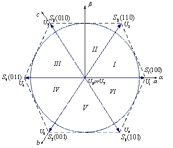
Figure 2. Space Vector Voltage and Switching Pattern
The main advantage of the conventional DTC is by selecting the proper voltage space vectors i.e. flux and torque both can be controlled at the same time according to the load requirements. Selection of the voltage space vector is dependent on the flux and torque errors as shown in Table 1.
Table 1. Switching table
|
Flux error position |
Torque error position |
Sector I |
Sector II |
Sector III |
Sector IV |
Sector V |
Sector VI |
|
1 |
1 |
U2 |
U3 |
U4 |
U5 |
U6 |
U1 |
|
0 |
U7 |
U0 |
U7 |
U0 |
U7 |
U0 |
|
|
-1 |
U6 |
U1 |
U2 |
U3 |
U4 |
U5 |
|
|
0 |
1 |
U3 |
U4 |
U5 |
U6 |
U1 |
U2 |
|
0 |
U0 |
U7 |
U0 |
U7 |
U0 |
U7 |
|
|
1 |
U5 |
U6 |
U1 |
U2 |
U3 |
U4 |
In conventional DTC, the entire sampling period is comprised of only one switching vector. Hence, the motor torque may exceed the upper/lower torque limit, even if the error is small. By introducing more than one vector within the sampling period, reduction of the torque ripple can be achieved.
Proposed Direct torque control
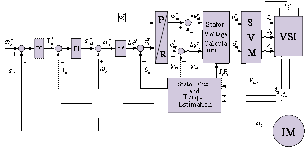
Figure 3. Block diagram of the Proposed DTC
The structure of proposed DTC for induction motor is shown in Figure 3. The hysteresis comparators and voltage-switching table of conventional DTC is eliminated. Prediction of the reference of stator flux linkage, calculation of the reference of voltage space vector and SVPWM technique are added.
In this technique, the torque control is achieved by maintaining the constant amplitude of reference stator flux. From Equation (7) the torque control is directly performed by controlling torque angle change, which is the angle between stator and rotor flux vectors and keep stator and rotor flux vectors at constant amplitude. From (7) torque equation is replaced as (8) using the same principle in [5] and [6], the instantaneous electromagnetic torque can be derived as:
|
|
(8) |

where ![]() is the time constant.
is the time constant.
From Equation (8), the quantity ![]() is nothing but slip
is nothing but slip![]() between the
stator flux angular frequency
between the
stator flux angular frequency ![]() and rotor angular frequency
and rotor angular frequency![]() . The slip
angular frequency can be written as:
. The slip
angular frequency can be written as:
|
|
(9) |
By substituting Equation (9) in (8), the instantaneous electromagnetic torque is given :
|
|
(10) |

From Equation (10), the relationship between the instantaneous electromagnetic torque and slip angular frequency is clear. The slip angular frequency can be rewritten as:
|
|
(11) |
where ![]() is the angle between stator flux vector
axis and rotor axis, and is the sampling time.
is the angle between stator flux vector
axis and rotor axis, and is the sampling time.
By substituting Equation (11) into (10), the modified instantaneous electromagnetic torque is given by:
|
|
(12) |

From Equation (12), the instantaneous electromagnetic torque control is performed by changing the value of slip angle witch is controlled by using direct stator flux control method. In Figure 4 the torque PI controller values are designed same as in [7].

Figure 4. Block diagram of the torque control loop
Direct Stator Flux Control Method
From Equation (12), the instantaneous electromagnetic
torque control is performed by changing the value of the slip angle ![]() which is
directly controlled by using direct stator flux control method.
which is
directly controlled by using direct stator flux control method.
In stator flux control method, the important task is
decoupling the amplitude and angle of stator flux vector. From the above block
diagram (Figure.3), reference torque is generated from speed pi regulated, ![]() is the
torque error between the reference torque and estimated real torque. In order
to compensate this error, the angle of stator flux linkage must be increased
from
is the
torque error between the reference torque and estimated real torque. In order
to compensate this error, the angle of stator flux linkage must be increased
from ![]() to
to![]() as shown in
Figure 5, where the stator flux angle is the required change in stator flux
angle.
as shown in
Figure 5, where the stator flux angle is the required change in stator flux
angle.
From the below phase diagram, Figure
5, ![]() ,
therefore:
,
therefore:
|
|
(13) |
from (13) ![]() is nothing but change in slip angle
is nothing but change in slip angle![]() , which is
generated from torque pi controller.
, which is
generated from torque pi controller.
Therefore required reference stator flux vector in polar form is given by:
|
|
(14) |
where ![]() is maintained constant at rated value
and angle of the reference stator flux is calculated from Equation (13).
Required slip angel is written by:
is maintained constant at rated value
and angle of the reference stator flux is calculated from Equation (13).
Required slip angel is written by:
|
|
(15) |
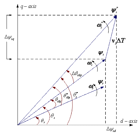
Figure 5. Control of stator flux linkage
Estimated actual flux magnitude is:
|
|
(16) |
|
|
(17) |
The reference flux vector is given by:
|
|
(18) |
|
|
(19) |
The flux error is given by:
|
|
(20) |
|
|
(21) |
The reference space voltage vector is given by:
|
|
(22) |
|
|
(23) |
where ![]() is the sampling time.
is the sampling time.
Reference flux components are calculated from Equations
(18) and (19). ![]() is the flux error between reference flux
and estimated actual flux. In order to compensate the flux error, voltage
components are calculated from the model of voltage space vector. Using this
reference voltage components, time signal are calculated as explained in [8]. Time signals generate the pulses for control the voltage source inverter (VSI). Within this sample the inverter is switched and made to remain at different switching states for different durations of time such that
the average space vector generated within the sampling period is equal to the
sampled value of the reference value.
is the flux error between reference flux
and estimated actual flux. In order to compensate the flux error, voltage
components are calculated from the model of voltage space vector. Using this
reference voltage components, time signal are calculated as explained in [8]. Time signals generate the pulses for control the voltage source inverter (VSI). Within this sample the inverter is switched and made to remain at different switching states for different durations of time such that
the average space vector generated within the sampling period is equal to the
sampled value of the reference value.
Simulation Results
Conventional DTC and proposed SVM DTC MATLAB models were developed for 3hp induction motor at 0.0004sec sampling time and VSI DC link voltage is 540V. The parameters of the induction motor are shown in Table 2:
Table 2. Parameters of the induction motor
|
Power |
2.2 kw |
|
Stator resistance Rs |
2.23Ω |
|
Rotor Resistance Rr |
1.15Ω |
|
Stator Inductance Ls |
0.21H |
|
Rotor Inductance Lr |
0.21H |
|
Mutual Inductance M |
0.1988H |
|
Phase voltage U |
220V |
|
Inertia J |
0.055Kgm2 |
|
Frequency f |
50Hz |
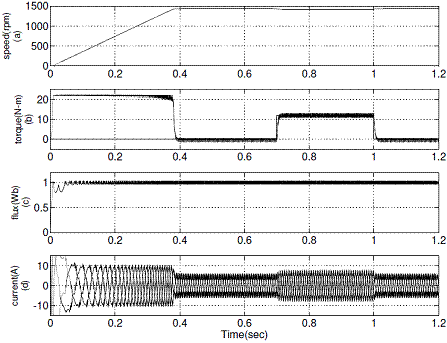
Figure 6. Simulation results of conventional DTC: (a) Variation of rotor speed from 0 rpm to 1440 rpm (b) A load torque of 12 N-m is applied at 0.7 sec and removed at 1 sec (c) Stator flux (d) d-axis current Id
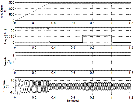
Figure 7. Simulation results of proposed DTC: (a) Variation of rotor speed from 0 rpm to 1440 rpm (b) A load torque of 12 N-m is applied at 0.7 sec and removed at 1 sec (c) Stator flux (d) d-axis current Id
The simulation results of conventional DTC and proposed DTC for forward motoring operation are shown in Figure 6 and Figure 7 respectively. It represents the motor developed torque at no-load and full load, stator flux and stator current at rated speed for conventional DTC and proposed DTC drives.
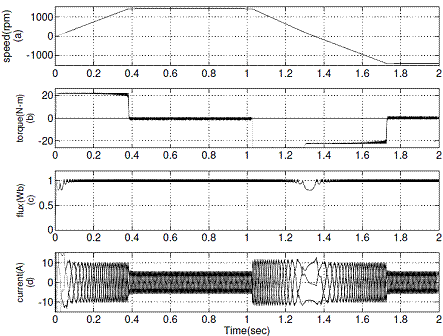
Figure 8. Simulation results of conventional DTC during speed reversal operation from +1440 rpm to -1440 rpm, (a) Rotor speed (b) Electromagnetic torque, (c) Stator flux (d) d-axis current Id
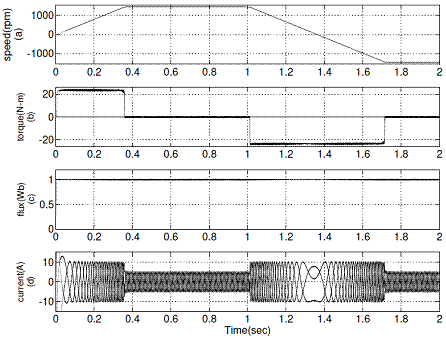
Figure 9. Simulation results of proposed DTC during speed reversal operation from +1440 rpm to -1440 rpm (a) Rotor speed (b) Electromagnetic torque (c) Stator flux (d) d-axis current Id
The reverse motoring operation of conventional DTC and proposed DTC are shown in Figure 8 and Figure 9 respectively.
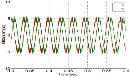
Figure 10. d-q stator current with conventional DTC
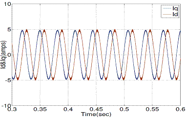
Figure 11. d-q stator current with proposed DTC
Figure 10 and Figure 11 show the steady state stator d-q current responses of conventional and proposed DTC respectively, operated at 1440 rpm.
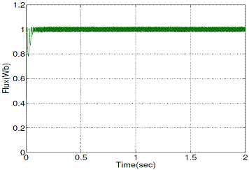
Figure 12. Stator flux magnitude with conventional DTC
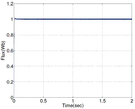
Figure 13. Stator flux magnitude with proposed DTC
Figure 12 and Figure 13 show the steady state stator flux magnitude responses of conventional and proposed DTC respectively, operated at 1440 rpm.
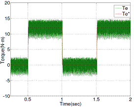
Figure 14. Estimated torque response when step load torque change from no-load to full load (012 Nm) with conventional DTC
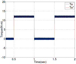
Figure 15. Estimated torque response when step load torque change from no-load to full load (012 Nm) with proposed DTC
Figure 14 and Figure 15 show the estimated torque responses of conventional and proposed DTC respectively, operated at 1440 rpm.
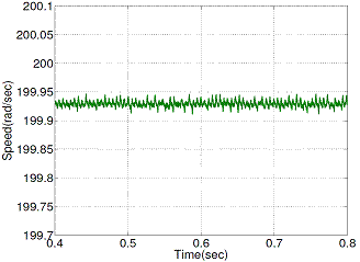
Figure 16. Speed ripple with conventional DTC scheme
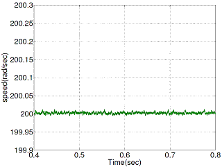
Figure 17. Speed ripple with proposed DTC scheme
Figure 16 and Figure 17 show the steady state rotor speed ripple responses of conventional and proposed DTC respectively, operated at 200 (rad/sec).
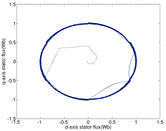
Figure 18. d-q stator flux locus with conventional DTC scheme
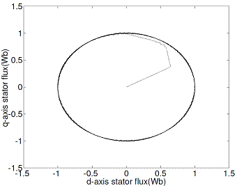
Figure 19. d-q stator flux locus with proposed DTC scheme
Figures 18 and 19 show a comparison of stator flux space vector obtained using conventional and proposed DTC methods.
![]()
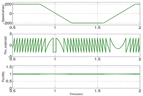
Figure 20.
Simulation results of the proposed DTC during speed reversal operation at 32
Hz (±200 rad/sec): (a) Stator flux angle,
![]()
![]() -axis flux; (b) stator flux
amplitude
-axis flux; (b) stator flux
amplitude
Figure 20 shows that during speed reversal operation, the angle of the stator flux is reversed but the magnitude is keep constant. Therefore the proposed method is based on a decoupling between the amplitude and angle of the stator flux vector control.
The performance of three-phase induction motor drive with conventional DTC and proposed DTC are illustrated in Figures 6-19.
Figures 11, 13 and 15 show appreciable reduction of current, flux and torque ripple has been obtained the proposed technique for DTC of induction motor.
Figures 13 and 15 show that the proposed DTC (PDTC) method stator flux and torque ripple level is reduced when compared with the conventional DTC (CDTC).
Table 3. Ripple Level
|
|
Flux(Wb) |
Torque (N-m) |
|
CDTC |
0.0210 |
4.2 |
|
PDTC |
0.0105 |
0.76 |
Table 3 gives the clear picture about the ripple level comparison between two methods (CDTC and PDTC).
Conclusion
In this paper, an effective algorithm is presented for direct torque and flux control of three-phase induction motor drive. It is proposed a decoupled control between the amplitude and angle of stator flux for generating the pulses for VSI.
Using MATLAB/SIMULINK the simulation of proposed and conventional techniques was carried out for DTC of 3hp three-phase inductions motor. In conventional DTC, within the sampling time only one voltage vector (i.e. instantaneous voltage vector) is applied to inverter to reduce the flux as well as torques errors. In the proposed technique, within the sampling time more than one voltage vector is applied to the inverter for reducing the flux and torque errors.
From simulation results, the proposed technique showed that the stator current, flux linkage and torque ripples are lesser than in the conventional technique.
References
4. Bose B.K., Modern Power Electronics and AC Drives, Englewood Cliffs, NJ: Prentice-Hall, 2001.
7. Yuttana Kumsuwana, Suttichai Premrudeepreechacharna, Hamid A. Toliyatb, Modified direct torque control method for induction motor drives based on amplitude and angle control of stator flux, Electric Power Systems Research, 2008, 78(10), p. 1712-1718.
9. Lascu C., Boldea I., Blaabjerg F., A Modified direct torque control for induction motor sensor less drive, IEEE Transactions on Industry Applications, 2000, 36(1), p. 122-130.
10. Schauder C., Adaptive speed identification for vector control of induction motors without rotational transducers, IEEE Transactions on Industry Applications, 1992, 28, p. 1054-1061.