Magnetization and Primary Injection Test of Current Transformer for Protective Relaying
Jacob TSADO
Department of Electrical and Computer
Engineering,
*Corresponding author e-mail: j.tsado@yahoo.com
Abstract
Emphasis is placed on the ability of current transformers to provide accurate operating current at normal system operation and other system disturbance to protective relay systems in high voltage power systems. This paper presents the results of a laboratory investigation of magnetization and primary injection test of current transformer; a basic requirement to ensure that a current transformer is in good condition and able to perform as it is designed to, before commissioned into service. The test carried out allows the magnetization curve to be deduced from the measured data. In addition, the current transformer was modelled by curve fitting the magnetization curve using MATLAB. The result obtained serves a guide for utility engineers who apply current transformers for protective relaying.
Keywords
Current transformer; Protective relay; Magnetization; Power system Engineers
Introduction
Current transformers (CT) are among the most commonly used items of electrical apparatus in power system protection schemes and yet surprisingly, there seems to be a general lack of even the most elementary knowledge concerning their performance characteristics and limitations among engineers who are continually using them [1, 2].
However, detail information concerning CT and voltage transformer (VT) performance characteristics and limitations are further [3, 4]. Figure 1 shows a simple arrangement of current transformer with bar primary.
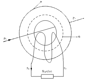
Figure 1. Current Transformer with Bar Primary
The importance of current transformers in the transmission and distribution of electrical energy cannot be over emphasized because upon the efficiency of current transformers and the associated voltage transformers that the accurate metering and effective protection of those distributions circuits and plants depend.
Current transformers isolate the secondary (relay, instrument and meter) circuits from primary (power) circuit and provide quantities in the secondary, which are proportional to those in the primary. The role of a current transformer in protective relaying is not as readily defined as that for metering and instrumentation. Whereas the essential role of a measuring instrument transformer is to deliver from its secondary winding a quantity accurately representative of the primary side, a protective transformer varies in its role according to the type of protective gear it serves. In recent times, the introduction of numerical protection relays and high speed signal processing has lead to high frequency transients being used for a wide range of for EHV, HV system [5, 6]. The success of these techniques relies on the availability of suitable current transformer.
Failure of a protective system to perform its function correctly is often due to incorrect selection of the associated current transformer [7-9]. Hence, current and voltage transformers must be regarded as constituting part of the protective system and must be carefully matched with the relays to fulfil the essential requirements of the protection system.
There are two basic groups of current transformers, namely; measurement CT’s and protective CT’s the requirements of which are often radically different. It is true in some cases that same current transformer may serve both purposes of metering and protection in modern practice. This is the exception rather than the rule: The measuring current transformer is required to retain a specified accuracy with respect to the load currents being measured. While the protective current transformer must be capable of providing an adequate output over a wide range of fault conditions, from a fraction of full load to many times full load current.
This paper addresses the issue of basic test necessary to ensure proper selection and applications of current transformer in power system protection system.
Material and Method
Current Transformer Designation
Current transformers are usually designed as either class ‘P’ or class ‘X’. Class ‘P’ is usually specified in terms of:
· Rated Burden;
· Class (5Por 10P);
· Accuracy Limit Factor.
Consider the following example of a class ‘P’ CT 15VA 10P20.
This means that the CT has an external secondary burden of 15VA the composite error will be 10% or less for primary current up to 20 times rated current.
The relationship between rated burden (VA) and accuracy limit factor (ALF) is given by Equation 1[2]:
|
|
(1) |
but when the internal voltage drop in the C.T needs to be taken into account, we have:
|
|
(2) |

where Vk is the knee voltage and IN is the normal CT current.
Class ‘P’ type of CT are general used for instantaneous over current protection and relays with Inverse Definite Minimum Time Lag (IDMTL) characteristics.
Class ‘X’ is specified in terms of each of the following characteristics:
· Rated primary current;
· Turns ration (The error in turns ration shall not exceed);
· Knee-point voltage;
· Exciting current at the knee point voltage (and/or + 0.25%) at a stated percentage thereof;
· Resistance of secondary winding.
Class ‘X’ specifications is general used in application of differential relay unit systems where balancing of outputs from each end and of the protected plant is vital.
Laboratory Tests
The laboratory tests used the experimental scheme as shown in Figures 2 and 3. A signal generator was used to provide the current to an input of the CT. Each of the output (secondary) windings of the CT was used to provide the output current to be measured by a high precision meter.
|
|
|
|
Figure 2. Sketch of CT magnetizing characteristic test arrangement |
Figure 3. Sketch of CT primary injection test arrangement |

The potential problems of residual magnetic flux were minimized by gradually raising the voltage applied to the CT until the CT core reaches magnetic saturation. The source voltage is then progressively decreased to zero after which the actual test is then carried out.
These measures, together with the careful layout of the test equipment and associated wiring were taken so that the test would only reflect the current transformer characteristic devoid of error.
Results and Discussion
The tests were carried out on five cores GET oil impregnated current transformers which were new and others which were removed from the system after some years of service for the purpose of understanding the CT characteristic and suitability for protection co-ordination. The tests result on the new five core CT's were of particular interest since these could be fitted and therefore be used for field investigations into the operation of future designs. Tables 1 show the current transformer ratio for CT core 1 determined from the primary injection test. The result revealed the accuracy limit factor of the CT core 1, with zero percentage error at 15A and 30A primary injected currents.
|
Primary Injected Current (A) |
Measured Sec. Current (A) |
Calculated Ratio |
Expected Ratio |
|
10 |
0.007 |
1428.5 |
1500 |
|
15 |
0.010 |
1500.0 |
1500 |
|
20 |
0.014 |
1428.0 |
1500 |
|
25 |
0.017 |
1470.5 |
1500 |
|
30 |
0.020 |
1500.0 |
1500 |
Tables 2 show the current transformer ratio for CT core 2 determined from the primary injection test. The result revealed the accuracy limit factor of the CT core 2, with 4.76 % and 0% percentage error at 15A and 30A respectively.
Table 2. CT ratio of Core 2
|
Primary Injected Current (A) |
Measured Sec. Current (A) |
Calculated Ratio |
Expected Ratio |
|
10 |
0.007 |
1428.57 |
1500 |
|
15 |
0.0105 |
1428.57 |
1500 |
|
20 |
0.014 |
1428.57 |
1500 |
|
25 |
0.017 |
1470.59 |
1500 |
|
30 |
0.020 |
1500.00 |
1500 |
The current transformer ratio for CT core 3 is shown in Table 3 determined from the primary injection test. The result revealed the accuracy limit factor similar to that of CT core 1at 15A and 30A, this however is not enough evident that the cores can be used for the same application.
Table 3. CT ratio of Core 3
|
Primary Injected Current (A) |
Measured Sec. Current (A) |
Calculated Ratio |
Expected Ratio |
|
10 |
0.0068 |
1470.59 |
1500 |
|
15 |
0.010 |
1500.00 |
1500 |
|
20 |
0.0138 |
1449.28 |
1500 |
|
25 |
0.017 |
1470.59 |
1500 |
|
30 |
0.020 |
1500.00 |
1500 |
The result from the test on the CT core 4 is shown in Table 4. For these test, the percentage error at 15A and 30A primary injection current is 0.31% and 1.31% respectively. The errors obtained are actually insignificant since the measured secondary current may not be measured 100% accurately.
Table 4. CT ratio of Core 4
|
Primary Injected Current (A) |
Measured Sec. Current (A) |
Calculated Ratio |
Expected Ratio |
|
10 |
0.0065 |
1538.45 |
1600 |
|
15 |
0.0094 |
1595.74 |
1600 |
|
20 |
0.0130 |
1538.46 |
1600 |
|
25 |
0.0158 |
1582.28 |
1600 |
|
30 |
0.019 |
1578.95 |
1600 |
A similar test was conducted on CT core 5; the result obtained is presented in Table 5.
There is steady error of 2.34% from the primary injection current of 20A through 30A in the core ratio obtained. This results of the entire core revealed that, the CT is still in good stated to be used. However, the Primary injection currents test alone cannot guarantee a specific application of the cores, magnetization test now become necessary.
Table 5. CT ratio of Core 5
|
Primary Injected Current (A) |
Measured Sec. Current (A) |
Calculated Ratio |
Expected Ratio |
|
10 |
0.0065 |
1538.46 |
1600 |
|
15 |
0.0094 |
1595.74 |
1600 |
|
20 |
0.0128 |
1562.50 |
1600 |
|
25 |
0.016 |
1562.50 |
1600 |
|
30 |
0.0192 |
1562.50 |
1600 |
The measurements of currents against voltages are shown in Figure 4. The Figure shows the magnetizing characteristic curve for each of the CT’s core. The characteristic curve enable the protection engineer classified the CT core for a particular application. Core 2 and 3 has a similar characteristic of virtually a flat response from 120V to 240V, these cores are suitable for metering application since they saturate faster, while core 4 and 5 are suitable for differential protection scheme and core 1 may be used for over-current protection scheme.
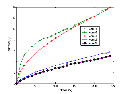
Figure 4. Magnetization Curves of the CT's
The magnetization curve obtained from the measurements of currents against voltages is curve fitted using MATLAB, the results from these techniques give valuable input and also serves as an object of comparison with the development of new current transformer for practicing protection engineers whom may be interested in the design and construction of current transformers. Figure 5 shows the result of the curve fitting for core 1, considering the y axis to be the current and x axis to be the voltage, the following expression give the standard relationship between the current and voltage for CT core 1. The quadratic model is:
|
I = -4.7E-0005V2 + 0.033V + 0.39 |
(3) |
While, the fourth order polynomial model is:
|
I = -2.4E-0005V4 + 1.5E-006V3 - 0.0003V2 + 0.054V + 0.096 |
(4) |
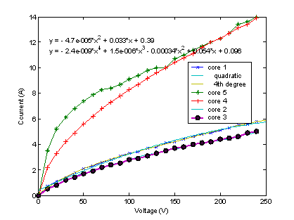
Figure 5. Quadratic and 4th degree polynomial curve fitted of core 1
The curve fitted for CT core 2 is shown in Figure 6; the quadratic model is given as follows:
|
I = -4.5E-0005V2 + 0.029V + 0.30 |
(5) |
While, the 4th order polynomial model is:
|
I = -1.2E-009V4 + 8.5E-007V3 - 0.00023V2 + 0.043V + 0.096 |
(6) |
The curve fitted for CT core 3 is shown in Figure 7; the quadratic model is given as follows:
|
I = -4.2E-005V2 + 0.029V + 0.24 |
(7) |
While, the 4th polynomial model is:
|
I = -9.6E-010V4 + 6.9E-007V3 - 0.0002V2 + 0.041V + 0.061 |
(8) |
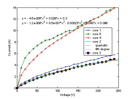
Figure 6. Quadratic and 4th degree polynomial curve fitted of core 2
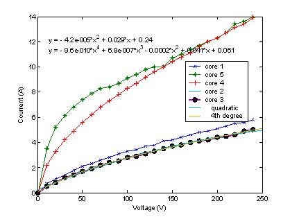
Figure 7. Quadratic and 4th degree polynomial curve fitted of core 3
The curve fitted for CT core 4 is shown in Figure 8; the quadratic model is given as follows:
|
I = -0.00013V2 + 0.081V + 1.4 |
(9) |
While, the 4th order polynomial model is ;
|
I = -8.9E-009V4 + 5.4E-006V3 - 0.00012V2 + 0.015V + 0.43 |
(10) |
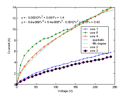
Figure 8. Quadratic and 4th degree polynomial curve fitted of core 4
The curve fitted for CT core 5 is shown in Figure 9; the quadratic model is given as follows:
|
I = -0.00013V2 + 0.075V + 3.0 |
(11) |
While, the 4th polynomial model is ;
|
I = -2.3E-008V4 + 1.3E-005V3 - 0.00026V2 + 0.23V + 0.81 |
(12) |
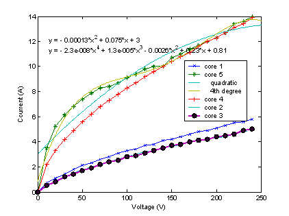
Figure 9. Quadratic and 4th degree polynomial curve fitted of core 5
Conclusion
This paper has provided a window into the basic problems of selecting right current transformer for the application. The result obtained from the test carried out established an operating baseline for future system troubleshooting; it enables the determination of transformer ratio since this may not be found on the name plate of the current transformer.
The paper provides a basis to go deeper into the selection procedure for the utility engineers who apply current transformer for protective relaying.
References
1.
2. Tsado J., Investigation of Power System Protection Scheme in the Nigerian 330kV Transmission Network, a PhD Thesis submitted to Electrical Engineering Department, University of Benin, Benin City, 2007.
3. Hodgkiss J.W., Transient Response of Current Transformers, IEEE Special Power Publication 76CH1174-2 PWR, 1976.
4. Douglass D. A., Current Transformers Accuracy with Asymmetric and High Frequency Fault Currents, IEEE Trans PAS, 1981, 100, p. 1006-1011.
5. Bo Z.Q., Redfern M.A., Weller G.C., Positional Protection of Transmission Lines Using Fault Generated High Frequency Transient Signals, IEEE Trans. Power delivery, 2000, 15(3), p. 888-894.
6. Batty D.W.P., Thomas D.W., Christopolus C., A Novel Unit Protection Scheme based on Superimposed Currents, Sixth International Conference on Developments in Power System Protection, Nottingham, IEE Publication, 1997, 434, p. 83-86.
7. IEEE Guide for the Application of Current Transformers Used for Protective Relaying Purposes, IEEE STD, 1996, C37-110.
8. Bridger. B., Polarity Markings on Instrument Transformers, Powell Electric Technical Brief No. 34, 1992.
9. IEEE Power System Relaying Committee Report., Transient Response of Current Transformers, IEEE Publication 76 CH 1130-4, 1976.