Microcontroller Based Low Cost Portable PC Mouse and Keyboard Tester
Ganesh Sunil NHIVEKAR* and Ravidra Ramchandra MUDHOLKAR
Department of Electronics,
E-mail: gonioelect@gmail.com*
Abstract
This article describes design of low cost embedded system to test standard PS2 mouse and keyboard based on AVR microcontroller.
Keywords
Mouse; Keyboard; Microcontroller; AVR microcontroller.
Introduction
Many mouse and keyboards uses PS2 (AT) device interface protocol [1]. When a computer is used for the purpose of testing using software programs, each time the computer needs to be rebooted to test them. This process need be repeated for each mouse or keyboard to be tested. This method is time consuming also need PC as resource. The microcontroller based portable system has been developed as described in this paper to test standard mouse and keyboard without need of PC as resource.
The Hardware interface
The available PS2 port connectors for standard mouse and keyboard are of two types, the 5-pin DIN connector of “5D” type, and the smaller six-pin mini-DIN. The pin assignments are shown in Figure 1. The physical interface between the device and the host is shown in Figure 2. Two signal lines are used, clock and data. The signal lines are open connector, which required external pull-up resistors. This allows either the device or the host system to force a line to low level.
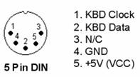
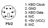
Figure 1. Connector pin assignments
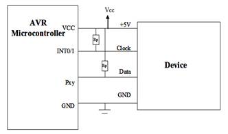
Figure 2. Interface between the host and the device
PS2 keyboards use the same protocol as the PS2 mouse [1]. Keyboard and mouse use a serial protocol with 11-bit frames; the timing for the data transferred from the device to the host is shown in Figure 3. The device writes a bit on the Data line when Clock is high, and it is read by the host when Clock is low. The protocol is: one start bit (always 0), eight data bits, one odd parity bit and one stop bit (always 1).
Figure 3. Timing for device to host communication
The Host to PS2 device protocol is initiated by taking the data line low. However to prevent the conflict data, device Clock line kept low for more than 100us. Then pull data line low, and release clock line. The timing for the communication from the host to the device is shown in Figure 4.
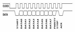
Figure 4. Timing for host to device communication
The system circuit
Central Processing Unit (CPU)
The CPU used in the system is ATMEL AVR microcontroller, ATMEGA8 provides on chip internal RC oscillator which is used to lower the cost increase the efficiency and reliability. ATMEGA8 also have low power consumption which makes it a best for battery powered portable systems. Internal RC oscillator is calibrated at 8 MHz.
The Display Circuit
The system uses LCD module for display results. The module has on-board display controller, which relieves the main microcontroller from manually generating dot-matrix character display. The display unit is composed of 16×2 dot matrix alphanumeric LCD. The LCD is configured in 4-bit mode with read-write control (WR) pin grounded. This configuration requires less number of I/O pins of microcontroller, typically 6 only. The circuit diagram shown in Fig. 5 reveals actual pin connections of the system.
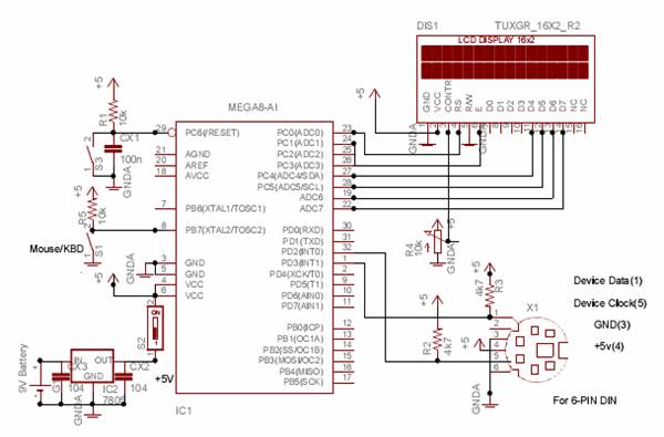
Figure 5. Full Functional Hardware Schematic of Microcontroller based low cost portable PC mouse and keyboard tester
Software Description
In microcontroller based system, software design is also a subtle task as that of hardware design. The software for the CPU is written in embedded-C language with the help of AVR studio IDE tool. Figure 6 shows the basic flow chart of the system software and the Figure 7 revel the main function of the device program along with necessary included header files.
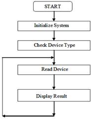
Figure 6. Basic flow chart of the system
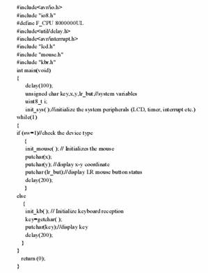
Figure 7. Main function in device software
The logical behavioral flow of the system is as follows: When the system is powered-on, the initialization part of the system software configures various on-chip peripherals such as timers, interrupts etc. and initializes the externally interfaced LCD. This initialization sequence puts these resources into a known state. Mouse and keyboard have different device ID. Once initialized the system first checks interfaced device type using key (sw1), then it manually reads device ID and based on that it determines device type. Error is displayed if both are not matched.
Keyboard
The AT keyboard has a scan code associated with each key. When a key is pressed, this code is transmitted. If a key is held down for a while, it starts repeating. The repeat rate is typically 10 per second. When a key is released, a “break” code ($F0) is transmitted followed by the key scan code. For most of the keys, the scan code is one byte. Some keys like the Home, Insert and Delete keys have an extended scan code, from two to five bytes. The first byte is always $E0. This is also true for the “break” sequence, e.g., E0 F0 xx…
AT keyboards are capable of handling three sets of scan codes, where set two is default. The present system only use set two. Keyboard reception is handled by the interrupt function INT0_interrupt. The reception will operate independent of the rest of the program.
The algorithm for keyboard tester is: Store the value of the data line at the leading edge of the clock pulse. This is easily handled if the clock line is connected to the INT0 pin. The interrupt function will be executed at every edge of the clock cycle, and data will be stored at the falling edge. After all bits are received, the data can be decoded. This is done by calling the decode function. For character keys, this function will store an ASCII character in a buffer. It will take into account if the shift key is held down when a key is pressed. Other keys like function keys, navigation keys (arrow keys, page up/down keys etc.) and modifier keys like Ctrl and Alt are ignored. The mapping from scan codes to ASCII characters are handled with table look-ups, one table for shifted characters and one for un-shifted. The received ASCII character is displayed on LCD.
Mouse
The program initializes the mouse with some commands, and then enters a loop where about every 200 milliseconds requests to the mouse data about switches' state and X-Y movement since last request [3]. The received data from mouse is processed by microcontroller and display the X-Y coordinate, and right-left button pressed on LCD. Software communication is also managed to verifying timeout, framing and parity errors, and coding from mouse [4-6]. Timeout error, as an example, can occur also in the case the mouse is disconnected, it doesn't answer, there is a broken wire etc.; in such case error is displayed on LCD.
Conclusion
This is an inexpensive, portable design allows the users to quickly test mouse and keyboard with flexibility of compatibility with other mouse and keyboard technologies. The total cost for system is less then 4 dollars. Looking at these factors the above mentioned system will be preferred over the conventional PC based test system.
References
1. Chapweske A., PS/2 Mouse/Keyboard Protocol, 2001, Available at: http://www.Computer-Engineering.org
2. Simandl P., PC keyboard, 1999, Available at: http://www.simandl.cz/stranky/elektro/keyboard/keyboard_a.htm
3. Fahey C., PS2 mouse and BASIC Stamp computer, Available at: http://colinfahey.com/index_en.html
4.
Barr M., Programming Embedded Systems in C and C++, 1st edition,
5. Nhivekar G.S., Mudholkar R.R., Data Logger and Remote Monitoring System for Multiple Parameter Measurement Applications, Journal of Electrical and Electronics Engineering, 2011, 4(1), p. 139-142.
6. Nhivekar G.S., Mudholkar R.R., Implementation of fuzzy logic control algorithm in embedded microcomputers for dedicated application, International Journal of Engineering, Science and Technology, 2011, 3(4), p. 276-283.