Modelling and Simulation of TCPAR for Power System Flow Studies
Narimen Lahaçani AOUZELLAG*, Lyes BENKHELLAT, Samir MAHLOUL
Department of Electrical Engineering, Faculty of Technology, University A. Mira Béjaia, Algeria.
E-mail: nlahacani@yahoo.fr
* Corresponding author: Phone: 213-72-32-30-01; Fax: 213-34-21-50-06
Abstract
In this paper, the modelling of Thyristor Controlled Phase Angle Regulator ‘TCPAR’ for power flow studies and the role of that modelling in the study of Flexible Alternating Current Transmission Systems ‘FACTS’ for power flow control are discussed. In order to investigate the impact of TCPAR on power systems effectively, it is essential to formulate a correct and appropriate model for it. The TCPAR, thus, makes it possible to increase or decrease the power forwarded in the line where it is inserted in a considerable way, which makes of it an ideal tool for this kind of use. Knowing that the TCPAR does not inject any active power, it offers a good solution with a less consumption. One of the adverse effects of the TCPAR is the voltage drop which it causes in the network although it is not significant. To solve this disadvantage, it is enough to introduce a Static VAR Compensator ‘SVC’ into the electrical network which will compensate the voltages fall and will bring them back to an acceptable level.
Keywords
TCPAR and SVC devices; Newton Raphson method; Power flow control; Voltage regulation.
Introduction
Energy exchanges across the networks have increased significantly due to the liberalization of the electricity market. This increase was further accentuated the vital need for good transmission capacity of these networks and led to the search for new ways to improve management and coordination of transfers monitoring and control systems. But in the case of large networks with transfers of powers increased, this task becomes difficult and can present a problem.
The power electronics, has been relatively present in electrical networks, begins to make its appearance significantly. It has enormous potential for, among other things, the interfacing of producers to the grid, the adjustment of active and reactive powers forwarded through the lines, networks interfacing and DC distribution and improvement of the power network quality.
To solve the problems of power flow, the concept of the FACTS devices, are the collection thyristor based controllers, including phase shifter, advanced static VAR compensator, dynamic brake, modulator series capacitor, load tap changer and fault current limiter [1-5], offer an alternative to the traditional means of regulation. These devices based on the electronics power, make it possible to control the voltage level and/or the power transited in the lines of an electrical network. FACTS devices can be used both for the control of the active and reactive powers [5-7] or the voltage. The goal of any FACTS devices study is to measure their impact on the state of the electrical networks into which they are introduced [5,8]. Their principal function is to improve the static and dynamic properties of the electrical networks and that by increasing the margins of static and dynamic stability and to allow the power transit to the thermal limits of lines.
To study the impact of insertion of TCPAR in the electrical network, it is necessary to establish the network state (magnitude and angle voltages at buses and powers injected and forwarded in the lines) before and after its introduction. This leads to calculate the power transit by using an iterative method such as Newton-Raphson [9,10]. Undertaking a calculation without the introduction of TCPAR followed by a calculation with the modifications induced by the integration of this device into the network, makes it possible to compare the results obtained in both cases and thus assesses the interest of the use of FACTS devices.
Insertion of the TCPAR in the Electrical Network
There are several devices which control the power transit [11-13], by adjusting the angle between the voltages at the ends of the transmission line. They do not generate or consume power, but merely change the transit. It is modelled by a voltage source, which represents the branch series, and of a power source representing the branch shunt.
In computing the power
flow, these devices are modelled using an ideal transformer with complex
transformation ratio![]() .
.
In the case of the TCPAR, the transformation ratio is expressed as:
![]() (1)
(1)
Thus, it only affects the voltage angle while its magnitude remains constant.
For a TCPAR introduced into a transmission line as shown in the figure 1, a voltage VTr is introduced and it is expressed as a fraction of the voltage Vm at the bus m to which it is connected. It can be written as:
![]() (2)
(2)
And as,
![]() (3)
(3)
Then,
![]() (4)
(4)
Or,
 (5)
(5)
TCPAR Modelling
For a TCPAR introduced at the bus m of a transmission line as shown in figure 1, the equation which defines the relationship between the currents injected into the line and the voltages at buses t and k is:
Figure 1. TCPAR inserted in a line
 (6)
(6)
Such as,
 (7)
(7)
Knowing that,
![]() (8)
(8)
Considering (2) and (3), the new expressions of the currents become:
 (9)
(9)
The admittance matrix of the new line has the form:
 (10)
(10)
Influence of TCPAR on the Network
To reflect the effect of TCPAR on the network, it is inserted into the line and changes its admittance matrix and, consequently, it changes the network admittance matrix. The elements that come into consideration when this change will be detailed later:
Modification of the admittance matrix
The modified matrix of the line where the TCPAR is inserted at bus m can be written as:
 (11)
(11)
Only elements related to buses k and m of the line affect the matrix of the network. The two elements related to the voltage are used to model an active power injected by the TCPAR. The nodal admittance matrix of the network is modified as follows.
 (12)
(12)
![]() are
the elements of the matrix before the introduction of TCPAR, with:
are
the elements of the matrix before the introduction of TCPAR, with:
 (13)
(13)
The power injected at bus which is connected TCPAR is modified to account for contribution of the admittance matrix elements of the line relating to the voltage injected by the TCPAR.
 (14)
(14)
Modification of the Jacobian matrix
For TCPAR connected to a line between the buses m and k, the power forwarded through this line, viewed from the side of the active bus t, is written as follows:
![]() (15)
(15)
Such as,
 (16)
(16)
So,
![]() (17)
(17)
And knowing that,
![]() (18)
(18)
So,
![]() (19)
(19)
And,
![]() (20)
(20)
Then,
![]() (21)
(21)
Thus,
![]() (22)
(22)
The active and reactive powers flowing through this line are:
 (23)
(23)
On the other hand, the power injected at node k is given as follows:
 (24)
(24)
Then,
 (25)
(25)
From equation (25) the active and reactive powers can be expressed as follows:
 (26)
(26)
Such as, γtt and γtk, are the phase shifts of the admittances ytt and ytk respectively.
 (27)
(27)
![]() (28)
(28)
The active and reactive powers are as follow:
 (29)
(29)
The insertion of TCPAR in the line connecting the buses m and k, generates modifications in the matrix system for the calculation of the power flow as follows:
 (30)
(30)
The Jacobian matrix is given by:
 (31)
(31)
Simulation Results
Figure 2 shows the 5 bus test system used in this paper, where the bus bars are numbered from 1 to 5 and the lines from 1 to 7. The bus bar 1 is the slack bus, bus bar 2 is a P, V and buses 3 to 5 are a P, Q buses. The Newton Raphson algorithm is applied in power flow calculation.
Figure 2. The studied network structure
Data at buses and lines before inserting the TCPAR are grouped in Tables 1 and 2. The bus voltage magnitudes and angles and the active and reactive powers forwarded in the lines before inserting the TCPAR are represented in Tables 3 and 4 respectively.
Table 1. Bus data
|
Bus |
V (pu) |
δ (°) |
Generation |
Load |
||
|
P (pu) |
Q (pu) |
P (pu) |
Q (pu) |
|||
|
1 |
1.000 |
0.000 |
0.000 |
0.000 |
0.000 |
0.000 |
|
2 |
1.020 |
0.000 |
0.400 |
0.000 |
0.200 |
0.100 |
|
3 |
1.000 |
0.000 |
0.000 |
0.000 |
0.450 |
0.150 |
|
4 |
1.000 |
0.000 |
0.000 |
0.000 |
0.400 |
0.050 |
|
5 |
1.000 |
0.000 |
0.000 |
0.000 |
0.600 |
0.100 |
Table 2. Line data
|
Line |
1-2 |
1-3 |
2-3 |
2-4 |
2-5 |
3-4 |
4-5 |
|
R (pu) |
0.0200 |
0.0800 |
0.0600 |
0.0600 |
0.0400 |
0.0100 |
0.0800 |
|
X (pu) |
0.0600 |
0.2400 |
0.1800 |
0.1800 |
0.1200 |
0.0300 |
0.2400 |
|
B (pu) |
0.0600 |
0.0600 |
0.0400 |
0.0400 |
0.0300 |
0.0200 |
0.0600 |
Table 3. Voltage magnitudes and angles at the buses
|
Bus |
1 |
2 |
3 |
4 |
5 |
|
Voltage (pu) |
1.000 |
1.0200 |
0.9711 |
0.9712 |
0.9673 |
|
Angle (°) |
0.000 |
-3.3941 |
-5.7398 |
-6.1192 |
-7.0576 |
Table 4. Powers forwarded in the lines
|
Line |
1-2 |
1-3 |
2-3 |
2-4 |
2-5 |
3-4 |
4-5 |
|
P (pu) |
0.8968 |
0.4064 |
0.2482 |
0.2808 |
0.5503 |
0.1873 |
0.0626 |
|
Q (pu) |
-0.2997 |
-0.0199 |
0.0622 |
0.0527 |
0.0908 |
-0.0722 |
-0.0281 |
To see the effect of TCPAR on the power flow in the lines, it is inserted in two different locations. To achieve this objective, the case of a network in voltage drop is studied and the TCPAR is introduced in line 1 then in line 7. The TCPAR in presence of another FACTS device, the Static Var Compensator (SVC), will also be studied. Its principal function is to inject reactive power, according to the thyristor firing angle, into the network, which helps to support the system voltage profile [14-16].
Effects on the forwarded powers
The TCPAR allows, due to phase shift introduced it, to control the power carried in the line where it is inserted. It may well force the active power to pass in a line rather than in others and thus to properly distribute power in the network.
To verify this property, the TCPAR inserted into a line 1 then in line 7. The angle θ of the factor μ is varied in a range from 0° to 24°. The results obtained are summarized and interpreted in the following.
Insertion of a TCPAR in line 1
Line 1, before introduction of TCPAR, is overloaded while other lines carry only very low values of power. To remedy this, the TCPAR is inserted for different values of the angle θ. Figure 3 shows the variation in power transited on the lines according to the angle of the transformation factor of TCPAR.

Figure 3. Active powers forwarded in the lines
The impact of the insertion of TCPAR on the active power flowing through the line 1 is detailed in the following figure.

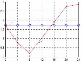
Figure 4. Active power forwarded in line 1 before and after inserting the TCPAR
Figures 3 and 4 show that the TCPAR inserted into a line 1 changes the distribution of active power transited through the lines. Indeed, for θ ranging from 0° to 8°, the TCPAR reduces 85% of the active power transported by line 1. This decrease is accompanied by increased powers transited in the other lines of the network. Thus, the power flowing through the line 7 increases. By against, the power in lines 2 and 6 are decrease as the angle θ increases.
Above 8°, the power increases in line 1, this increase reached 60% for an angle of 24°. Lines 2 and 6 continued to show lower powers while those transited through other lines increase with increasing θ.
Insertion of a TCPAR in line 7
The TCPAR is now inserted into the line 7 to increase the transmitted power by this line which is often charged. The angle θ is varied over the same interval as before to observe the variation of power forwarded in the lines, Figure 5 illustrates this variation.

Figure 5. Active powers forwarded in lines
The variation of the power forwarded by line 7 is shown by the following figure, before and after inserting the TCPAR.

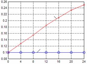
Figure 6. Active power forwarded in line 7 before and after inserting the TCPAR
The insertion of TCPAR in line 7 can increase the active power through the line where it is inserted, while the strength decrease active power traveling via other lines as shown in figure 5. Indeed, figure 6 shows that the TCPAR increases the active power transited through line 7. This increase reached 150% for an angle θ of 24°, this proves the effectiveness of TCPAR to control the power flow through the lines.
The TCPAR can also unload the lines transiting high active power as line 1. Figure 5 evaluates the decrease, for an angle of 12°, the active power transited by this line is reduced by about 64%.
Effects on the voltage
In order to study the behaviour of the TCPAR with the introduction of an SVC where the firing angle of the thyristors is set at 170° to provide the reactive power necessary for the voltage drop compensation and to improve the voltage level. The case of the introduction of an SVC into line 6 for a TCPAR inserted in line 1 will be considered. The parameters of the SVC are given in references [14-16].

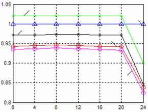
Figure 7. Voltage magnitudes at buses with presence of TCPAR in line 1
Figure 7 illustrates the effect of TCPAR on the voltage magnitudes at buses. It is clear that magnitudes fall with increasing θ. To remedy this, an SVC is inserted into the line 6 (connecting buses 3 and 4) to observe its effect on voltages. Figure 8 shows this improvement.

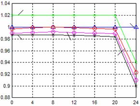
Figure 8. Voltage magnitudes at buses with presence of TCPAR and SVC

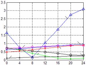
Figure 9. Active powers forwarded in the lines after inserting the SVC
Figure 7 shows that the TCPAR causes deterioration in the voltage level at the buses that are already below the tolerance limit for the voltage drop, this is a problem in terms of power quality. The introduction of SVC in line 6 improves compensation. Indeed, figure 8 shows that the voltages at buses 3, 4 and 5 are now above 0.95pu which is the quality limit fixed.
On the other hand, figure 9 shows that the insertion of the SVC has virtually no effect on the behavior of TCPAR and its ability to control the active power transited through the lines.
Conclusion
This paper is devoted to study the insertion of TCPAR device in an electrical network and its ability to control the active power transited through the lines. Indeed, the observation of active power flow in the lines before and after insertion of a TCPAR shows that it can charge some lines and discharge other in order to alter the powers of transit through the network.
The TCPAR allows increasing or decreasing the power flowing in the line where it is inserted considerably which makes him ideal for this use case. And knowing that it does not inject active power, it offers a good solution with less power consumption.
A side effect of TCPAR is the voltage drop that causes in the network although it is not important. To remedy this disadvantage, the insertion of an SVC in the network allows the voltage regulation and compensates the voltage drop to an acceptable level. This insertion does not affect the capacity of TCPAR as has been verified by the results presented.
References
1. Hingoran N.G., High power electronics and flexible AC transmission system, IEEE power engineering review, 1988, p. 3-4.
2. Hingorani G., Power electronics in electric utilities: role of power electronics in future power systems, Proceedings of the IEEE, 1988, 76(4), p. 481-482.
3. Hingorani G., et al., Future role of power electronics in power systems, Proceedings of international symposium on power semiconductor devices, Yokohama, 1995.
4. Song Y., Johns A., Flexible AC transmission systems (FACTS), IEE Power and Engineering Series 30, 1999.
5. Crappe M., Dupuis S., Les systèmes flexibles de transport de l’énergie électriques, Stabilité et sauvegarde des réseaux électriques, 2003, chapter 4, p. 149-204.
6. Noroozian M., Andersson G., Power flow control by use of controllable series components, IEEE transactions on power delivery, 1993, 8(3), p. 1420-1429.
7. Edris A., et. al., Controlling the flow of real and reactive power, IEEE Computer Applications in Power, January 1998.
8. Acha E., et al., FACTS, modelling and simulation in power networks, Chichester, John Wiley and Sons, 2004.
9. Acha E., et al., A Newton-type algorithm for the control of power flow in electrical power networks, IEEE Trans Power Syst, 1999, 12(4), p. 1474-1480.
10. Acha E., et al., The unified power flow controller: a critical comparison of Newton-Raphson UPFC algorithms in power flow studies, IEE Proc. Gener. Trans. Distrib., 1997, 144(5), p. 437-444.
11. Heydt G.T., Gotham D.J., Power flow control and power flow studies for systems FACTS devices, IEEE Transactions on Power Systems, 1998, 13(1), p. 60-65.
12. Radman G., Raje R.S., Power flow model/calculation for power systems with multiple FACTS controllers, Elsevier, Electrical power systems research, 2006.
13. Domínguez-Navarro J.A., Bernal-Agustín J.L., Díaz A, Requena D, Vargas E.P., Optimal parameters of FACTS devices in electric power systems applying evolutionary strategies, Electrical Power and Energy Systems, 2007, 29(1), p. 83-90.
14. Aouzellag Lahaçani N., Benkhellat L., Mahloul S., Mendil B., Impact of the SVC in the electrical network, International conference on electrical engineering design and technologies ICEEDT’08, Hammamet, Tunisia, 2008.
15. Lahaçani N.A., Mendil B., Modelling and Simulation of the SVC for Power System Flow Studies: Electrical Network in voltage drop, Leonardo Journal of Sciences, 2008, 13, p. 153-170.
16. Lahaçani N.A., Mendil B., SVC Modelling and Simulation for Power System Flow Studies: Electrical Network in Over Voltage, Jee Journal of Electrical Engineering, 2009, 9.