Formation and Characterization of Alaminum Thin Films Produced by Laser Induced Forward Transfer Technique
Nafie A. ALMUSLET*1 and Mohammed O. AWADALLAH2
1 Institute of laser Sudan University of Science and Technology (www.sustech.edu), almogran - Khartoum / Republic of Sudan, P. O. Box (407).
2 Department of Physics Red Sea University, Sudan.
Email: mnmfa2008@yahoo.com; msman41@yahoo.com
*Corresponding author: Phone: 00249126738127; Fax: 00249183765635
Abstract
Picoseconds Nd YAG laser was used in this work to irradiate pure samples of Aluminum (Al) and produce plasma. The plasma plume was deposited as thin films, using Laser Induced Forward Transfer (LIFT) technique, on two different types of substrate; the first one from copper and the second one from agate (SiO2). The thin films were characterized using scanning electron microscope (SEM) and Energy Dispersive Analysis of X-rays (EDAX), in addition to scratch and scotch-tape for adhesion test. The effects of laser power density, the target thickness and the type of substrate on the homogeneity and adhesion of the films were investigated. The best conditions were: 2∙1013 W/cm2 laser power density, 2 µm target thickness and agate substrate. Al thin films with high quality were deduced using these conditions.
Keywords:
Aluminum thin films; Laser plasma interaction, Laser Induce Forward Transfer.
Introduction
Plasma can be defined as a gas in which atoms have been ionized to a considerable degree and for this reason plasma often is referred to as an ionized gas [1]. Plasmas are encountered in stars and the interstellar medium. On our earth plasmas also exist in light bulbs, discharges, flat-screen televisions, and are created in short-pulse laser experiments. Lasers with high power densities incident on a material can interact with the surface and ionized some of its atoms creating a plasma environment. The main important phenomena in this case is the plasmas laser absorption due to different mechanisms such like rapid inverse bremsstrahlung heating of the plasma electrons [2].
Features of plasmas produced by laser are heavily dependent on certain conditions such as incident laser intensity, irradiation spot size, atmosphere gas composition and pressure. It is also true that these parameters vary drastically with axial or radial distance from the target surface under the same irradiation conditions. The key parameters of laser-ablated plasma plumes are density and temperature. At early times, the characteristics of the plume are governed primarily by electron contributions to temperature and density. The temperature can be estimated for the entire duration of the expansion of the plume with the aid of x-ray and visible spectroscopy [3, 4].
The principle of Laser Produced Plasma (LPP) involves all the physical processes of laser-material interaction during the impact of the high-power radiation on a solid target. It also includes the formation of the plasma plume with high energetic species, the subsequent transfer of the ablated material through the plasma plume in the laser direction.
At sufficiently high energy density and short pulse duration, all elements in the target surface are rapidly heated up to their evaporation temperature. Materials are dissociated from the target and ablated out with stoichiometry as in the target. The instantaneous ablation rate is highly dependent on the flounce of the laser irradiating the target. Different plasma applications are listed below [5]:
Plasma arc for welding, cutting and steel refinery processes.
Material fabrication: single crystal growth, fabrication of small particles and powders.
Plasma chemistry.
Semiconductor processing.
Formation of thin films.
The most important techniques used as plasma ablation for thin films formation are Pulsed Laser Deposition (PLD) and Laser Induce Forward Transfer of material (LIFT).
The general principle of the LIFT process is outlined in Figure (1). The thin film of the material to be transferred is deposited on a substrate of metal or crystal [6]. The receiving substrate is placed parallel and facing the target at a very short distance. This distance can vary from incontact to several micrometers. The laser wavelength is selected to the range of minimum substrate absorption and maximum target absorption. The type of laser (i.e. its wavelength, intensity, focal spot size and pulse length or scanning speed), the type of the material (i.e. optical absorption coefficient, thermal diffusivity) and the geometry of all components determine the quality of the transferred material arrives onto substrate [7, 8].
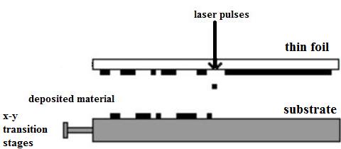
Figure 1. Scheme of the laser-induced forward transfer (LIFT) process
A shock wave is created in a medium that suffers a sudden impact, like LIFT, or in a medium that releases large amounts of energy in a short period of time (e.g. high explosives). When a high-power laser interacts with matter, very hot plasma is created. This plasma exerts a high pressure on the surrounding material, leading to the formation of an intense shock wave, moving into the interior of the target. The momentum of the out-flowing plasma balances the momentum imparted to the compressed medium behind the shock front. The thermal pressure together with the momentum of the ablated material drives the shock wave [9]. Since the passage time of the shock is short in comparison with the disassembly time of the shocked sample, one can do shock wave research for any pressure that can be supplied by a driver, assuming that a proper diagnostic is available [10].
In 1974 the first direct observation of a laser-driven shock wave was reported [11]. The science of high pressure is usually analyzed in a medium that has been compressed by a one-dimensional shock wave. The starting points in analyzing the one-dimensional shock waves are the conservation laws of mass, momentum and energy [12]. Shocks play a dominant role in the compression phase of plasmas, especially in coating by plasma.
In this work thin films were formed from aluminum targets using plasma ablation by Laser Induced Forward Transfer of metal (LIFT) as a dynamic technique for coating. Then these thin films were characterized to obtain the optimum parameters for producing good quality homogeneous films.
Materials and Methods
The components of the setup used for LIFT experiments are shown in figure 2.
Figure 2. Sketch diagram of the experimental setup used for LIFT experiments
The Nd:YAG Laser source
Q-switched frequency doubled Nd:YAG laser (model ND 40, supplied from spectra physics company - USA), was used in this study. The technical specifications of this laser are listed in the table (1).
Table 1. Specifications of Nd:YAG laser model ND40
|
Laser model |
Q-switched Nd:YAG Laser |
|
Laser wavelength |
532 nm |
|
Pulse energy |
15 - 35 mJ |
|
Pulse width |
40 ps |
|
Repetition rate |
1 - 10 Hz |
The targets
The used targets were foils of Al. Each target foil was fixed on the substrate by using double sticker tape. These foils were of 1, 2, and 3 µm thickness and 2cm×2cm dimensions. The adjustment of target-substrate distance provides an opportunity to improve the deposition quality. In this system, the target foil was placed in contact, parallel to the substrate.
The substrates
Two different types of substrates were used for deposition in LIFT experiments. They were copper and agate which is semi-pellucid crystallized quartz of SiO2. Each substrate was well cleaned in distilled water and then dried, before the laser shoot, in order to remove the impurities and residuals from their surface to get pure deposition.
Thin films characterization
The characterization of the films was done using Scanning Electron Microscopy (SEM); the ratio of the chemical components was investigated by Energy Dispersive Analysis of X-rays (EDAX) while the film thickness was measured by travelling microscope. The SEM investigation was carried out by (FEL Quanta 200, Netherlands Company) equipped with Energy Dispersive Analysis of X-ray (EDAX).
Procedure of LIFT deposition experiments
The distance between the target and the substrate was not varied and always fixed in the in-contact manner. The source-substrate pair was placed in a miniature cell parallel to each other under a normal atmosphere. This miniature cell was fixed onto a manual controlled linear translation stage, allowing a maximum of 45 mm movement, by means of manual feed-throw. Thus, serial deposition of metal-islands and isolated dots were deposited as thin films. Scratch and scotch-tape were used to test the adhesion degree of the films on the substrate surface.
Results
The effect of different LIFT parameters on the homogeneity of the deposited films was investigated. The results of sets of experiments are presented and discussed here.
The ablation threshold effect on the film homogeneity
It was important to specify the minimum laser intensity needed to produce the transformation of material from target to the copper substrate provided that no damage (crater) is introduced into the substrate. The intensity threshold was examined in same circumstances for the used materials using a single laser pulse and it was found to be, more or less, around 1.5×10¹³ W/cm2. For intensity equal to the transfer threshold, the achieved deposition was accumulated in one point and the agglomerates became denser in the central region of the transferred films. This made the morphology of the films very rough. At higher laser intensity, compared to the threshold mentioned above, a deep crater on the substrate was existed and the deposited film was re-ablated again by the remaining part of the laser pulse; therefore no deposition was achieved, as shown in figures (3) and (4). Here, the target was put exactly at the focal point of the lens.
The low crater depth of 0.0307 mm of the deposited film in figure (3.b) is an encourageing result to be completed by the EDAX analysis program to prove the enhancement of the deposition using 2×10¹³ W/cm2 laser intensity and 2µm target thickness as optimum parameters. In figure (3.a) low crater depth of 0.0098 mm was created. In figure (3.c), because higher laser intensity was used, deep crater depth was created and the deposited film was badly affected as summarized in table (2).
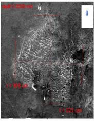
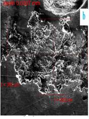
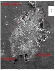
Figure 3. SEM images of Al plasma deposited on Cu substrate, showing the laser intensity influence on the deposition quality. The corresponded laser intensity for each image was;
(a): 1×10¹³W/cm2, (b): 2×10¹³W/cm2 and (c): 3×10¹³W/cm2
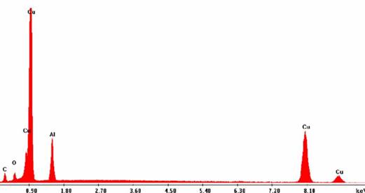
Figure 4. EDAX spectrum of Al plasma deposited on Cu substrate. The spectrum shows a symmetric shape of Al peak corresponding to image (b) in figure (3) and other peaks for Cu as a substrate
A symmetric shape of Al peak deposited on Cu substrate in figure (4) proved the film homogeneity using 2×10¹³ W/cm2 laser intensity.
Table 2. The effect of laser intensities on the deposition characteristics of Al thin films
|
Laser Intensity (×1013 w/cm2) |
Deposition diameter (µm) |
Crater depth (mm) |
Homogeneity |
Remarks/adhesion |
|
1 |
314.5 |
0.0098 |
Bad |
Bad |
|
2 |
307 |
0.0307 |
Good |
Good |
|
3 |
286.5 |
0.1023 |
Bad |
Bad |
The effect of target thickness
To investigate the effect of target thickness on the film homogeneity, and to know the optimum thickness, several experiments were carried out with different target thickness while all other parameters were fixed in the assumed optimum values. The laser intensity value was 2×10¹³ W/cm2 whilst the target was put 2 cm before the focal point of the lens. The deposition results are presented in figures (5), (6) and table (3).
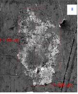
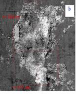
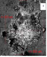
Figure 5. SEM images of Al plasma deposited on Cu substrate, showing the foil thicknesses influence on the deposition quality. The corresponded thickness for each image was; (a): 1µm, (b): 2µm and (c): 3µm
Figure (5) and table (3) insure the achievement of the deposition for all experiments with low crater depths but some defects were observed for each. In image (5.a), it was found that a large amount of the deposited material was not homogeneous and accumulated in one point. In image (5.c) the deposited material was distributed on a large area, but still not homogeneous. In image (5.b) there was a considerable enhancement in the film homogeneity. Confidently, it can be said that the achieved deposited film corresponded to the 2 µm as a target thickness was better than that achieved with other thicknesses.
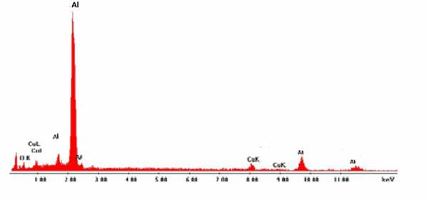
Figure 6. EDAX spectrum of Al plasma deposited on Cu substrate. The spectrum shows a symmetric shape of Al peak corresponding to image (b) in figure (5), and other peaks for Cu as a substrate.
Table 3. Enhancing the quality of Al deposition on the Cu substrate by changing the foil thickness
|
Foil thickness |
Crater depth (mm) |
Deposition diameter (µm) |
Homogeneity |
Remarks/adhesion |
|
1 |
Not measured |
251 |
Bad |
Good |
|
2 |
Not measured |
260 |
Very Good |
Very good |
|
3 |
Not measured |
327 |
Good |
Good |
Table (3) and image (b) in figure (5) made it clear that more homogenous film and less crater depth were achieved with 2µm thickness. Therefore, this thickness was considered to be one of the optimum values in this work. At a thickness of 1 µm the ablation threshold value reduced and hence the ejected particles have high temperature which might caused the re-ablation of the deposition and deep crater on the substrate as shown in the center of images (a) in figure (5). For the thickness of 3 µm, the threshold became high and the ejected particles have low temperature and hence accumulated in one point as presented in image (c) of figure (5).
The effect of substrate
Set of experiments was carried out to investigate whether the achieved values of the optimum parameters are valued for substrate other than copper. All parameters were kept in the optimum values mentioned before whilst the Al foils thickness was varied as shown in figures (7) and (8).
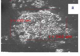
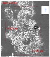
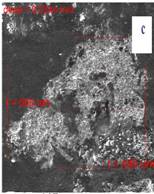
Figure 7. SEM amages of Al plasma deposited on agate substrate, showing the foil thicknesses influence on the deposition quality. The corresponded thickness for each image was; (a): 1µm, (b): 2µm and (c): 3µm
Figure (7) proves the achievement of the homogeneious deposition using the same optimum parameters for the agate substrate as well as for copper substrate.
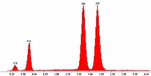
Figure 8. EDAX spectrum of Al plasma deposited on agate (SiO2). The spectrum shows a symmetric shape of Al peak corresponding to figure (7.b), and peaks for agate substrate
A symmetric shape of Al peaks deposited on agate substrate in figure (8) proved the film homogeneity using 2×10¹³ W/cm2 laser intensity and 2µm target thickness as optimum parameters. Figure (7) and table (4) show the homogeneous deposition for all experimental set with low crater depth (i.e. in the range of 0.01 mm scale). Here, a good enhancement in the film homogeneity was appeared from EDAX image in figure (8) beside better adhesion than before. This means that the use of the agate as a substrate gave better results than the copper.
Table 4. Enhancing the deposition of Al on the agate substrate by changing the foil thickness
|
Foil thickness (µm) |
Deposition diameter (µm) |
Crater depth (mm) |
Homogeneity |
Remarks/adhesion |
|
1 |
397 |
0.053 |
Good |
Good |
|
2 |
615 |
0.0120 |
Good |
Exeleant |
|
3 |
550.5 |
0.0244 |
Good |
Good |
It is clear that the deposition was good and homogeneous on the agate, therefore the used values (laser and target parameters) were optimum not only for copper substrate, but valued also for agate substrate. All the above deposition pattern have a well-adhering features.
Discussion
For the achieved results it can be said that in the case of power density equal 2x10¹³ W/cm2 the ejected plume, and hence the deposited pattern, followed the irradiating pulse Gaussian spatial profile. For both cases of high and low intensities the velocity and the ejected plume did not follow a Gaussian shape. This is attributed to the increased absorption of laser energy in a non-linear heat effects which appeared as a damage or crater in the substrate surface in the case of high laser intensities.
It is important to interpret these results and find how the ejected material temperature can affect the homogeneity of the deposited film. The dependence of the deposition on the plasma temperature come from the fact that the laser pulse heats the interface of the foil, resulting in a melt front that propagates in the direction of propagation of the incident laser beam, at that time the material at the interface is superheated beyond its boiling point and the resulting vapor-induced pressure propels material forward toward the substrate [13, 14].
From the analysis of the obtained results mentioned above, it can be concluded that LIFT is an effective ablation process that takes place during the energy transfer from the electronic system to the ions as a result of heat effect leading to the formation of a shock pressure at the foil-substrate interface. In addition, the use of 2 μm target thickness enabled the transferred materials to flow and coalesce, forming uniform and continuous coatings upon reaching the substrate in order to create a more homogeneous transferred pattern.
The concurrent observation that the morphology and size of the transferred films, which were changed within laser intensity scale, was a strong indication that electron-phonon interactions and the subsequent heating of the lattice was the major mechanism responsible for the observed morphological changes. So the ablated and deposited areas were subject to the heating effect resulted a distorted morphology [15]. Another problem for the creation of uniform thin films was the presence of droplets or nanoclusters. Splashing can occur when high pressure regions appear near the molten surface of the target, sending some particles out with enough energy to reach the substrate [16]. Adhesion of the deposited films was very good. It was not possible to remove it from the substrate even when applying a sticking tape (the so-called tape test which is simple but largely used to test the adhesion of deposited films). This result seems encouraging about LIFT technique as a possible approach satisfying the needs of industrial applications.
Conclusions
From the obtained results one can conclude that:
§ The LIFT threshold for Al thin films was found to be around 1 to1.5×1013W/cm2.
§ The optimum parameters for achieving homogeneious film were 2 μm target thickness, 2×10¹³ W/cm2 laser intensity, target-substrate in-contact and targets out of the focal point of the lens (defocusing).
§ Very good films adhesion can be reached in LIFT technique.
§ Using agate as substrate led to better results than using substrste of copper.
References
1. Anthony L.P., Physics of the plasma universe, New York, Springer, Verlag, 1992.
2. Dendy R., Plasma Physics: An Introductory Course, Cambridge, Cambridge University Press, 1994.
3. Miller J.C., Haglund R.F., Laser Ablation and Desorption, U.S.A., Academic Press, 1998.
4. Gondal M. et al., Determination of Toxic Metals in Petroleum, Cultivated Land and Ore Samples Using Laser-Induced Breakdown Spectroscopy, Bull Environ Contam Toxicol, 2007, 78, p. 270-274.
5. Rebut P.H., Plasma Physics Control Fusion, U. S. A., Academic press, 2006.
6. Kyrkisa K.D., Andreadakia A.A., Papazogloub D.G., Zergiotia I., Direct Transfer and Microprinting of Functional Materials by Laser Induced Forward Transfer, Recent Advances in Laser Processing of Materials, U. S. A., Elsevier Ltd, 2006.
7. Sakata H., Chakraborty S. and Wakaki M., Patterning of Bi2O3 films using laser-induced forward and backward transfer techniques, Microslectronic engineering, 2012, 96, p. 56-60.
8. Fortes F.J., Laserna J.J., Chronocultural sorting of archaeological bronze objects using laser-induced breakdown spectrometry. Analytica Chimica Acta, 2005, 554, p. 136-143.
9. Frank P., Stewart J.S., Lippert T., Boneberg J., Leiderer P., Laser-induced ablation dynamics and flight of thin polymer film, Applied Physics A: Materials Science & Processing, 2011, 104, p. 579-582.
10. Laserna J.J., Spectrochemical study for the in situ detection of oil spill residues using laser-induced breakdown spectroscopy, Analytica Chimica Acta, 2010, 683, p. 52-57.
11. Steinberg D.J., Equation of State and Strength Properties of Selected Materials, USA, UCRL Livermore, 1996.
12. Zeldovich Y.B., Rizer Y.P., Physics of shock waves and high temperature hydrodynamic phenomenon, U.S.A., Acadimic press, 1966.
13. Shafranov V.D., Reviews of Plasma Physics, Volume 24, Berlin, Springer-Verlag, 2008.
14. Fardel R., Nagel M., Nuesch F., Lippert T., Wokaun A., Energy Balance in a Laser-Induced Forward Transfer Process Studied by Shadowgraphy, J. Phys. Chem. C, 2009, 113, p. 11628-11633.
15. Seong Y., Fang, Y.Y., Jagdish P.S., Preliminary evaluation of laser induced breakdown spectroscopy for slurry samples, Spectrochim. Acta Pt. B, 2008, 64, p. 113-118.
16. Flores C.A., et al., Fractionation of petroleum resins by normal and reverse phase liquid chromatography, Fuel, 2006, 85, p. 1842-1850.