Robust Speed Control of a Doubly Fed Induction Motor using State-Space Nonlinear Approach
Tarik MOHAMMED CHIKOUCHE1*, Samir HADJRI2, Abdelkader MEZOUAR1, and Tahar TERRAS1
1 Electrical Engineering Department, Intelligent Control and Electrical Power System Laboratory (ICEPS), Djillali Liabes University, Sidi-Bel-Abbes, 22000, Algeria.
2 Electrical Engineering Department, Genie Electrical Laboratory (LGE), Moulay Tahar University, Saida, 20000, Algeria.
E-mails: tchikouche@yahoo.fr, shadjeri@yahoo.fr, a.mezouar@yahoo.fr, t_tahar@yahoo.fr
* Corresponding author: Phone: 00213 552757393; Fax: 0021348477230
Abstract
This paper presents a comparison between two controllers (fuzzy logic and variable gain PI) of the one part and the conventional PI on the other hand, used for speed control with indirect rotor flux orientation of doubly fed Induction Motor (DFIM) fed by two PWM inverters with separate DC bus link. By introducing a new approach for decoupling the motors currents in a rotating (d-q) frame, based on the state space input-output decoupling method, we obtain the same transfer function (1/s) for all four decoupled currents. Thereafter and in order to improve the performances of the machines control, the VPGI and fuzzy logic controllers with five subsets were used for the regulation speed. The Results obtained in Matlab/Simulink environment show well the effectiveness of the technique employed for the decoupling and the speed regulation of the machine.
Keywords
Doubly fed induction motor (DFIM); Input output decoupling; Field-oriented control; Modelling; Variable gain PI controller; Fuzzy logic controller, Conventional PI controller.
Introduction
The progress accomplished, in the few past years, in the power electronics and digital fields makes the Doubly Fed Induction Machine (DFIM) an industrial standard due to its low cost and high reliability [1, 15]. Doubly Fed induction motor is an electrical three-phase asynchronous machine with wound rotor accessible for control. Since the power handled by the rotor side (slip power) is proportional to the slip, the energy requires a rotor-side power converter which handles only a small fraction of the overall system power [2]. In recent years, there has been a great amount of activity on back stepping control approach in AC drive fields [2].The non linear control approach has better precision and stability. However, its major problem of is its sensitivity to motor parameter variations and load disturbance.
The DFIM control issues are traditionally handled by fixed gain proportional integral (PI) controllers. However, the fixed gain controllers are very sensitive to parameter variations, cannot provide good dynamic performance. So, the controller parameters have to be continually adapted [3]. The variable gain PI and fuzzy logic controllers gives better results to parameter variations for nonlinear systems. So, the DFIM is an ideal candidate to test the performances of its regulators [5]. Fuzzy control technique does not need accurate system modelling. It employs the strategy adopted by the human operator to control complex processes and gives superior performance. The fuzzy algorithm is based on human intuition and experience, and can be regarded as set of heuristic decision rules [8, 18].
The present work concerns field-oriented control with variable gain PI and fuzzy logics controllers of doubly fed induction motor with state space decoupling method.The vector control of the DFIM with two independent converters has been studied recently in several works. The linearization of the nonlinear model of the machine can be done in different manners with various terms of compensation. In this paper a nonlinear state space is proposed to ensure the decoupling of the multi-variables system input-output that constitutes the DFIM.
Dynamic Model of DFIM
The dynamic model of the DFIM in a (d-q) synchronous rotating frame is given by the equations of the voltages:
|
|
(1) |

Expressions of the fluxes are given by:
|
|
(2) |

From (1) and (2) the all currents state model is written as follows:
|
|
(3) |

The mechanical equation is expressed by (4):
|
|
(4) |
with: ![]()
And the electromagnetic torque is given by:
|
|
(5) |
So, the equation for the speed variation becomes:
|
|
(6) |
Vector Control Strategy of DFIM by Decoupling State Space
a. Rotor Flux Oriented
The principle for this type of control consists in orienting the flux into the machine, to the rotor, to the stator or in the air gap. Conventionally, we work with an orienting on the d axis. The in quadrature axis will therefore carry the current that will participate in the creation of the electromagnetic torque in the machine [5], [9].
To realize the control law, the rotor flux orientation is chosen along the d axis (figure.1). Therefore, we obtain:
|
|
(7) |
Then it comes:
|
|
(8) |
The magnetization of the machine, allows, to impose the rotor flux module, so we distinguish two strategies [5]:
Working
with a unitary power factor to stator or to rotor, which implies that one of the two currents ![]() or
or
![]() will be null,whether:
will be null,whether:
![]()
Split the magnetizing current equally between the two converters, ie
![]()
whether:
|
|
(9) |
The
choice of![]() , gives the same expression for the flux to the stator
and to the air gap. In addition, the expression depends only on
, gives the same expression for the flux to the stator
and to the air gap. In addition, the expression depends only on![]() , and with a unitary power
factor at the rotor.
, and with a unitary power
factor at the rotor.

Figure 1. Rotor Flux Oriented on the d Axis
b. Currents Decoupling by State Space
b.1 Principle of the method
Consider the following multivariable system:
|
|
(10) |

The objective is to determine a state space of the form:
|
|
(11) |
![]() denotes the new
input vector, which decouples the
system, in a way that the output
denotes the new
input vector, which decouples the
system, in a way that the output ![]() (i=1
to m) depends only on the input v. The output
(i=1
to m) depends only on the input v. The output ![]() is written:
is written:
![]()
where ![]() is the ith row of
the matrix
is the ith row of
the matrix ![]() . Let us derive
. Let us derive ![]() a few times in order to bring up the command. We call characteristic index noted
a few times in order to bring up the command. We call characteristic index noted ![]() , the number of derivation it takes in order to bring up the command.
, the number of derivation it takes in order to bring up the command.
We then have successively for each output i:
|
|
(12) |

That we can still write in matrix form:
|
|
(13) |

That is:
|
|
(14) |
with ![]() ,
, ![]() and
and ![]() . We seek a control law
. We seek a control law
![]() such as
such as![]()
![]() . The looped system is
written:
. The looped system is
written:
|
|
(15) |
To obtain ![]() we must have
we must have![]() and
and ![]() . If the matrix
. If the matrix ![]() is invertible, the choice of :
is invertible, the choice of :
|
|
(16) |
Gives:
![]()
That is:
|
|
(17) |
b.2 Application to the DFIM
We search to exploit this method for decoupling the currents of the machine projected on a (d-q) rotating frame [5, 10, 16]. Starting from the expression (3) and choosing a state vector equal to the output vector, formed of four currents of the machine. The input vector is formed of supply voltages. Then we obtain the following expression:
|
|
(18) |
with:![]() the state vector
(for all currants) and
the state vector
(for all currants) and ![]() the input vector
voltages.
the input vector
voltages.
|
|
(19) |
|
|
(20) |


where:
|
|
|
The
choice of ![]() makes the system completely controllable and observable. In applying the
decoupling method on this system, it
follows that:
makes the system completely controllable and observable. In applying the
decoupling method on this system, it
follows that:
|
|
(21) |

![]() , therefore:
, therefore:
|
|
(22) |
The four currents
are decoupled and thus governed by the same transfer function in open loop![]() .
.
c. Design the Control Loops
c.1 Currents control
The currents are decoupled, and then we can consider a state space correction
with the method of placement of poles. The principal
schematic diagram of this correction is given by the figure 2.
Figure 2. Current Regulation by State Space
To ensure the same response for the current loop, the next choice can be adopted.
|
|
(23) |

So the transfer function of each current closed loop will be of the form:
|
|
(24) |
c.2 Speed Control
The mechanical equation is given by:
|
|
(25) |
The
orientation of the rotor flux on the d axis, and the hypothesis to working with![]() , confer on the electromagnetic torque
the following expression:
, confer on the electromagnetic torque
the following expression:
|
|
(26) |
As we
proceed to the magnetization of the machine before applying a speed reference, ![]() can be replaced by its
reference
can be replaced by its
reference ![]() in the relation (26), therefore:
in the relation (26), therefore:
|
|
(27) |
and
|
|
(28) |
Such
as ![]() is
the constant
torque.
is
the constant
torque.
Thus, the transfer function of the speed will be expressed by:
|
|
(29) |
The magnitude![]() plays the role of a
disturbance input for speed, the principal input being
plays the role of a
disturbance input for speed, the principal input being![]() . The block diagram of the regulation will be in conformity with that of figure
3.
. The block diagram of the regulation will be in conformity with that of figure
3.
Figure 3. Speed Control Chain
VPGI and Fuzzy Logic Controllers in Speed Control of DFIM
a. VPGI Controller
a.1 VPGI Controller Structure
A variable gain PI (VPGI) controller is a generalization of classical PI controller where the proportional and integrator gains vary along a tuning curve as given by figure 4. Each gain of the proposed controller has four tuning parameters [4]:
§ Gain initial value or start up setting which permits overshoot elimination.
§ Gain final value or steady state mode setting which permits rapid load disturbance rejection.
§ Gain transient mode function which is a polynomial curve that joints the gain initial value to the gain final value.
§ Saturation time which is the time at which the gain reach its final value.
§
The degree n of the gain transient mode polynomial function is defined as the degree of the variable gain PI controller.
Figure 4. Variable PI Gains Turning Curve
It e(t) is the signal input to the VPGI controller the output is given by :
|
|
(30) |

with:
|
|
(31) |
|
|
(32) |


where ![]() and
and ![]() are the initial and final value of the
proportional gain
are the initial and final value of the
proportional gain![]() , and
, and ![]() is the final value of the integrator gain
is the final value of the integrator gain![]() . The initial value of
. The initial value of ![]() is taken to be zero. It is noted that a classic
PI controller is a VPGI controller of degree zero.
is taken to be zero. It is noted that a classic
PI controller is a VPGI controller of degree zero.
The VPGI unit step response is given by:
|
|
(33) |

Figure 5 give the unit step response of a VPGI controller of different values of the degree n.
Figure 5. VGPI Step Response for Different Values of the Degree n
If ![]() (transient
region) the classical PI unit step response is a linear curve beginning at
(transient
region) the classical PI unit step response is a linear curve beginning at ![]() and finishing at
and finishing at![]() , whereas the VPGI unit step
response
, whereas the VPGI unit step
response ![]() varies along a polynomial
curve of degree
varies along a polynomial
curve of degree ![]() beginning at
beginning at ![]() and finishing at
and finishing at![]() .
.
If ![]() (permanent
region), the unit step responses of a PI and VPGI controller are both linear
with slope
(permanent
region), the unit step responses of a PI and VPGI controller are both linear
with slope![]() .
.
From these results, one can say that a VPGI controller has the same properties than a classical PI controller in the permanent region with damped step response in the transient.
A VPGI controller could then be used to replace PI controller when we need to solve the load disturbance rejection and overshoot problems simultaneously.
a.2 Setting method of the VPGI controller
Unlike the classical PI controller, tuning of the VPGI controller does not need compromising. Speed overshoot caused by high integrator gains could be eliminated by increasing either the saturation time or the degree of the controller. One can choose the final value of the integrator gain needed for the application and then tune the other controller parameters so as to eliminate speed overshoot.
Here is a proposed method of tuning a VPGI controller.
1. Choose a first
degree VPGI controller with a high value of  (rapid
load disturbance rejection).
(rapid
load disturbance rejection).
2.
Choose an initial value of the saturation time![]() .
.
3.
Determine ![]() and
and![]() for
speed overshoot elimination by using the following steps:
for
speed overshoot elimination by using the following steps:
·
Consider![]() to be constant and simulate the controlled system for a
small initial value of
to be constant and simulate the controlled system for a
small initial value of![]() .
.
·
Increase![]() gradually and simulate the controlled system again until
speed overshoot gets to its optimum. Choose
gradually and simulate the controlled system again until
speed overshoot gets to its optimum. Choose ![]() to
be the value of
to
be the value of ![]() that gives optimal overshoot.
that gives optimal overshoot.
·
Simulate the
controlled system for an initial value of ![]() equal
to the chosen value of
equal
to the chosen value of![]() .
.
·
Increase
gradually the value of ![]() and simulate the
controlled system again until speed overshoot is totally eliminated or gets to
its optimal value. If overshoot is totally eliminated y then
and simulate the
controlled system again until speed overshoot is totally eliminated or gets to
its optimal value. If overshoot is totally eliminated y then ![]() is obtained and the controller is
tuned.
is obtained and the controller is
tuned.
4.
If overshoot is not eliminated, then the value
of the saturation time ![]() is not sufficiency high, increase it gradually without exceeding a
limiting value and repeat step 3 until overshoot is totally eliminated.
is not sufficiency high, increase it gradually without exceeding a
limiting value and repeat step 3 until overshoot is totally eliminated.
5.
If at the limiting value of ![]() overshoot
is still not eliminated, then the degree of the controller is not high enough.
Increase it and repeat the controller tuning again.
overshoot
is still not eliminated, then the degree of the controller is not high enough.
Increase it and repeat the controller tuning again.
Using this tuning method with![]() , the tuned
VPGI controlled is given by:
, the tuned
VPGI controlled is given by:
|
|
(34) |
b. Fuzzy Logic Controller
The structure of a complete fuzzy control system is composed from the following blocs: Fuzzification, Knowledge base, Inference engine, Defuzzification. Figure 6 shows the structure of a fuzzy controller.
Figure 6. The Structure of a Fuzzy Logic Controller
The fuzzification module converts the crisp values of the control inputs into fuzzy values. A fuzzy variable has values, which are defined by linguistic variables (fuzzy sets or subsets) such as low, medium, high, slow where each is defined by gradually varying membership function. In fuzzy set terminology, all the possible values that a variable can assume are named universe of discourse, and fuzzy sets (characterized by membership function) cover whole universe of discourse. The shape fuzzy sets can be triangular, trapezoidal, etc [6, 11, 12].
A fuzzy control essentially embeds the intuition and
experience of a human operator, and sometimes those of a designer and
researcher. The data base and the rules form the knowledge base which is used
to obtain the inference relation R. The data base contains a description of
input and output variables using fuzzy sets. The rule base is essentially the
control strategy of the system. It is usually obtained from expert knowledge or
heuristic; it contains a collection of fuzzy conditional statements expressed
as a set of IF-THEN rules, such as:![]()
|
|
(35) |

were: ![]() is the input
variables vector, Y is the control variable, M is the
number of rules, n is the number fuzzy variables
is the input
variables vector, Y is the control variable, M is the
number of rules, n is the number fuzzy variables ![]() are the fuzzy sets.
are the fuzzy sets.
For given rule base of a control system, the fuzzy controller determines the rule base to be fired for the specific input signal condition and then computes the effective control action ( the output fuzzy variable) [7, 8, 17].
The composition operation is the method by which such a control output can be generated using the rule base. Several composition methods, such as max-min or sup-min and max-dot have been proposed in the literature.
The mathematical procedure of converting fuzzy values into crisp values is known as defuzzification. A number of defuzzification methods have been suggested. The choice of defuzzification methods usually depends on the application and the available processing power. This operation can be performed by several methods of which center of gravity (or centroid) and height methods are commons [7, 13, 19].
b.1 Fuzzy-PI controller
The fuzzy PI controller is basically an input/ output static non-linear mapping, the controller action can be written in the form [13]:
|
|
(36) |
The Fuzzy-PI output is:
|
|
(37) |
where: ![]() is the gain of the speed error,
is the gain of the speed error, ![]() is the gain of the
change of speed error,
is the gain of the
change of speed error, ![]() is the proportional factor,
is the proportional factor, ![]() is the integral
factor,
is the integral
factor, ![]() is the speed error,
is the speed error,
![]() is the change of the speed error,
is the change of the speed error, ![]() is the fuzzy
output. The Fuzzy-PI controller in vector control of Dfim is used as presented
in Figure 7.
is the fuzzy
output. The Fuzzy-PI controller in vector control of Dfim is used as presented
in Figure 7.
Figure 7. The Structure of a Fuzzy PI Controller in a Vector Control of Dfim
b.2 Knowledge Base Proposed
Figure 8 and 9
shows respectively the triangle-shaped membership functions of error ![]() and Change of error
and Change of error ![]() .The fuzzy sets are desingnated by the
labels: Negative big (NB), Negative medium (NM), Negative small (NS), Zero
(Z), Positive small (PS), Positive medium (PM), Positive big (PB)
.The fuzzy sets are desingnated by the
labels: Negative big (NB), Negative medium (NM), Negative small (NS), Zero
(Z), Positive small (PS), Positive medium (PM), Positive big (PB)
Figure 8. Membership Functions Distribution for Input Variables
Figure 9. Membership Functions Distribution for Output Variables
In this paper, the triangular membership functions, the max-min reasoning method, and the center of gravity defuzzification method are used, as those methods are most frequently used in many literatures [14, 20]. The inference strategy used in this system is the Mamdani algorithm.
Table1. Linguistic Rule Table
|
|
NB |
NM |
NS |
Z |
PS |
PM |
PB |
|
NB |
NG |
NG |
NG |
NG |
NM |
NP |
EZ |
|
NM |
NG |
NG |
NG |
NM |
NP |
EZ |
PP |
|
NS |
NG |
NG |
NM |
NP |
EZ |
PP |
PM |
|
Z |
NG |
NM |
NP |
EZ |
PP |
PM |
PG |
|
PS |
NM |
NP |
EZ |
PP |
PM |
PG |
PG |
|
PM |
NP |
EZ |
PP |
PM |
PG |
PG |
PG |
|
PB |
EZ |
PP |
PM |
PG |
PG |
PG |
PG |
All the membership functions (MFs) are asymmetrical because near the origin (steady state), the signals require more precision. Seven MFs are chosen for E, dE signals and for ouput. All the MFs are symmetrical for positive and negative values of the variables. Thus, maximum 7×7 = 49 rules can be formed as tabulated in Table 1 [7, 14].
Simulation Results
The DFIM used in this work is a 1.5 Kw-50Hz, whose parameters are reported in appendix. The global schema of the State-Space Nonlinear control of a doubly fed Induction motor Using variable gain PI and fuzzy logic controllers as presented in figure 10.
A. Fuzzy Speed Reversal of Rated Value
In order to make a comparison between the behavior of the conventional PI controller and that of the fuzzy logic and VPGI controllers, studied under different operating conditions, a direct start of the motor under no load is realized with a set point of 157 rad / s followed by an inversion of the rotation direction at time t = 3s, the external perturbations are introduced by a sudden application of a 10N.m nominal charge at t = 1 s and removed at t = 2s.
The results given by figures (11 12) show excellent performance in regulation for the variable-gain and the fuzzy logic controllers with a very good monitoring of the reference speed.
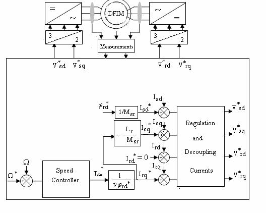
Figure 10. Block Diagram of Speed Control of Dfim using a State Space Nonlinear Approach
This will result in a much lower tracking error than that obtained using the conventional PI structure. Note also that the orientation of the rotor flux is fully realized; furthermore, the developed electromagnetic torque reproduces its reference satisfactorily.
It can also be noted that the low sensitivity and disturbance rejection are excellent for the two structures; both Fuzzy logic and VPGI controllers also provide better performance in terms of speed and time disturbance rejection.
B. Robust Control for Different Values of Rotor Resistance
In order to verifier the robustness of VPGI and Fuzzy-PI regulators under motor parameters variations, we have simulated the system with different values of the parameter considered and compared to nominal value (real value), one case is considered:
The rotor resistance variations (increase at 50% of nominal value rotor resistance). Figures (13-14) shows the responses speed, torque and rotor flux in the test of robustness for different values of rotor resistance. The results indicate that the VPGI and Fuzzy-PI regulators are insensitive to the resistance change, which results in the no influence on the torque and rotor flux.
For the robustness of control, an increase of the resistance does not have any effect on the performances of the proposed controllers.
Conclusions
In this paper, we presented the principle of speed control of a double-fed induction motor using a variable gain PI and a fuzzy logic speed controller.
Taking advantage of the accessibility of the current measurement of the motor, a new approach was discussed to allow the decoupling of its currents in a rotating (dq) frame.
This principle is based on an input-output decoupling by state space feedback that will lead to obtain very simple currents transfer functions, and therefore, a simplified calculation of the correction.
Subsequently, we demonstrated the improvement made by the variable gain PI and fuzzy logic speed controllers on the performance of the DFIM compared to the conventional PI controller. Simulation results demonstrate that VPGI and fuzzy-PI controllers outperforms the classical PI controller in speed control.
The simulation results showed a remarkable behaviour of the fuzzy-PI and variable gain PI controllers during regulation and tracking, with a significantly better disturbance rejection than the classic PI controller and a good performance towards robustness.
Appendix
DFIM Doubly Fed Induction Motor.
VPGI Variable Gain PI Controller.
s, r Stator and Rotor indices,
d,q Indices of the orthogonal components direct
and quadrature.
![]() Complex variable such as:
Complex variable such as:![]() .
.
![]() ,
,![]() Stator and Rotor resistances.
Stator and Rotor resistances.
![]() ,
,![]() Stator and Rotor inductances.
Stator and Rotor inductances.
![]() Stator and rotor time constant.
Stator and rotor time constant.
![]() Leakage factor
Leakage factor ![]() .
.
![]() Mutual inductance.
Mutual inductance.
![]() The
electrical rotor position.
The
electrical rotor position.
![]() Statoric
flux position, Rotoric flux position.
Statoric
flux position, Rotoric flux position.
![]() The mechanical rotor
frequency.
The mechanical rotor
frequency.
![]() Mechanical speed.
Mechanical speed.
![]() The electrical stator frequency.
The electrical stator frequency.
P Number of pole pairs.
![]() The
electromagnetic torque.
The
electromagnetic torque.
![]() The load
torque.
The load
torque.
![]() The
moment of inertia.
The
moment of inertia.
![]() The
friction coefficient.
The
friction coefficient.
Rated data of the simulated doubly fed induction motor:
Rated values: 1.5KW; 220/380V-50Hz;
Rated parameters:
![]()
![]()
![]()
![]()
![]()
![]()
Mechanical constants
![]()
References
1. Salloum G., Mbayed R., M. Pieterzak-David M., De Forme B., Mixed Sensitivity H∞ Control of Doubly Fed Induction Motor, 1-4244-0755-9/07/$20.00, IEEE 2007, 3, p. 1300-1304.
2. Yuan Li, Feng-You He, Zong-Bin Ye, Study on Sliding Mode Speed Control with Fuzzy Approch for Doubly-Fed Induction Motor, IEEE.Intrnational Conference on Conference on Control and Automation,Christchurch, New Zealand, December 9-11, p.2171-2175.
3. Chaiba A., Abdessemed R., Bendaas, M.L., Dendouga A., Performance of Torque Tracking Control For Doubly Fed Asychronous Motor Using PI and Fuzzy Logic Controllers, Journal of Electrical Engineering IEE, 2005, 5(2).
4. Miloudi A., Draou A., Gain PI Controller Design for Speed Controlled Induction Machine Drive, Conf. Rec. IEEE/IECON, Sevilla, Spain, 5-8 November, 2002.
5. Salloum G., Contribution at the Robust Control of Doubly Fed Induction Motor, Doctorat Thesis of National Institue Polytechnic of Toulous, France 2007
6. Prats M. A. M., Carrasco J. M., Galvan E., Sanchez J. A., Franquelo L. G., Batista C., Improving Transition between Power Optimisation and Limitation of Variable Pitch Wind Turbines using Fuzzy Control, In Proc, IEEE Industrial Electronics Society, Conf, 2000, 3, p. 1497-1502.
7. Attous D. B., Bekaka Y., Speed Control of a Doubly Fed Induction Motor using Fuzzy Logic Techniques, International Journal on Electrical Engineering and Informatics, 2010, 2(3), p. 179-191.
8. Allouae B., Abderrahmani A., Gasbaoui B., Nasri A., The Efficiency of Particle Swarm Optimisation Applied on Fuzzy Logic DC Motor Speed Control, Serbian Journal on Electrical and Engineering, 2008, 5(2), p. 247-262.
9. Drid S., Tadjine M., and Nait-Said M.S., Robust backcstepping vector control for doubly fed induction motor, IET Control Appl, 2007, 1(4), p. 861-868.
10. Vicatos M. S., Tegopoulos J. A., Doubly-Fed Induction Machine Differential Drive Model For Automobile, IEEE Transactions on Energy Conversion. Control Theory Appl., 2003, 18(2), p. 225-230.
11. Khojet S., Slama-Belkhogja E. I., Pietrzak-David M., de Formel B., A Fault Tolerant Operating System in a Doubly Fed Induction Machine under Inverter Short-circuit Faults Differential Drive Model, IEEE, 2006, p. 1125-1130.
12. Drid S., Tadjine M., Nait-Said M. S., Nonlinear Feedback control and torque optimization of a doubly fed induction motor, Journal of Electrical Engineering, 2005, 56(3-4), p. 57-63.
13. Chaari A., Soltani M., Gossa M., Comparative study between the conventional regulators and fuzzy logic controller: application of induction machine, International Journal of Sciences and Techniques of Automatic control and computer engineering IJ-STA, 2007, 1(2), p. 196-212.
14. Aissaoui M., Abid H., Abid A., Zeblah A., A Fuzzy Logic Controller for Synchronous Machine, Journal of Electrical Engineering, 2007, 58(5), p.285-290.
15. Nemmour A. L., Abdessamed R., Khezzar A., Louze L. and Boucherma M., The Input-Output Linearization Control Scheme for a Doubly-Fed Induction Motor Drive, 978-1-1736-0/08/$25.00, IEEE, 2008, p.1-6.
16. Vidal P-E., David M-P., Bonnet V., Mixed control strategy of a doubly fed induction machine, Springer-Vergal, 2007, p.337-346.
17. Zerikat M., Chekroun S., Mechernene A., A.Development and Implementation of High-Performance Variable Structure Tracking for Induction Motor Using Fuzzy-Logic Controller, International Review on Modelling and Simulations, 2010, 5(1), p. 160-166.
18. Negadi K., Mansouri A., Khatemi B., Real Time Implementation of Fuzzy Logic Based MRAS Observer for Speed Sensorless Vector Control of Induction Motor, International Review on Modelling and Simulations, 2010, 5(4), p. 1519-1528.
19. Abedinia O., Naderi Mohammad S., Jalili A., Mokhtarpour A., A Novel Hybrid GA-PSO Technique for Optimal Tuning of Fuzzy Controller to Improve Multi-Machine Power System Stability, International Review on Modelling and Simulations, 2011, 6(2), p. 863-873.
20. Ben Hamed Mouna, Abid Aicha, Sbita Lassaad, Neural Network Speed Sensorless Direct Vector Control of Induction Motor using Fuzzy Logic in Speed Control Loop, International Review on Modelling and Simulations, 2011, 6(5), p. 2237-2246.