Synchronization of Electronic Reactive Energy Counters for Measurement in Electric Power Systems in the Presence of Harmonics
Rabah DIABI
Electromechanical
E-mail: diabirabah@yahoo.fr
Abstract
In the world context, the measures done on the electric systems assume a crucial role for the invoicing of the energy, and also for the provision quality assessment in electric energy in a given network zone. Among the nuisances, the harmonic distortion has the most considerable weight, because of the non linear loads proliferation, which leads the non sinusoidal currents and voltages. Among the different problems led by the harmonic distortion but even resolute, there is two important aspects and bound to which intimately one must cope: the measure instrumentation synchronization and the reactive energy numbering with the electronic meters. With regard to the sizes measure defined by the IEEE norm, a virtual tool has been imagined, while using a technique in the domain time for the voltage and current fundamental extraction , on the basis of these works we led a survey the reactive energy electronic counters behaviour in harmonic distortion presence. The first results underline, that in sinusoidal regime the different methods with which are driven the reactive energy measure lead to the same result, while for the diet disrupted the electronic counters bring to a different answer
Keywords
Reactive Power; Harmonics;
Power Quality; Phase Locked
Introduction
In the new context of the liberalized market measurements on electrical power systems play a crucial role not only for energy billing, but also for assessing the quality of the collection and supply of electricity in a given section of the network and the possible allocation of responsibilities between users and operators, due to the presence of noise.
Among the different disorders, the harmonic distortion is very heavy, because of the proliferation in the network of non-linear loads that determine the onset of non-sinusoidal currents and voltages. Among the different open problems related to harmonics have addressed two aspects are linked to the synchronization of the instruments of power quality and reactive energy measurement with electronic meters.
Regarding the first aspect, currently, the main reference point for measuring power quality is the standard IEC 61000-4-30 [1], which describes the general characteristics of the methods of measurement and the accuracy specifications of the instruments, in reference to the measurement of the characteristics of the supply voltage. For measurements of harmonics and inter harmonics, see the IEC 61000-4-7 [2]. It defines the parameters to be measured to assess the level of harmonic distortion in a given cross-section measurement, through the amplitudes of voltage and current harmonics, as well as through global parameters such as the harmonic distortion factor (THD), calculated with respect to the total harmonic groups and subgroups or individual harmonics.
For instruments of class 1, the standard requires to carry out the measurement by means of the Discrete Fourier Transform (DFT) of a signal in steady state. As for the sampling, it sets the observation window to 200 ms (10 cycles of the fundamental 50 Hz) and requires synchronization, with a maximum error of ± 0.03%, in a frequency range of ± 5% around the nominal frequency of the system. Standard [2] does not provide specific guidance on the techniques to be used for synchronization nor on tests carried out for the evaluation of the error of synchronization, especially as regards the presence of any disorders, stationary or transient, on the input signal to the instrument. In this context, the authors developed an innovative synchronization system; capable of operating correctly in the presence of noise is stationary or transient. The characterization has been developed by developing appropriate test conditions.
The other issue addressed concerns the behavior of electronic meters for
reactive energy in the presence of harmonic distortion. These counters are now
replacing traditional meters induction, as compared to them, with greater
accuracy and stability, allow integration with the active energy meters and
measurement of most electrical parameters and can be used for the remote
reading and multi costing. As required by provisions in this regard, the
electronic meters for reactive energy, which can be constructively made in a
very different way, are designed for applications in the sinusoidal steady
state, where the reactive power and power factor are uniquely defined. In
reality, however, they are to operate in the presence of harmonics, due to the
increasing use of non-linear loads. Therefore, the evaluation of their
performance in distorted regime is essential, but the modes of proof required
by law in any case do not take into account the presence of harmonic
The deficiencies in the regulatory framework have just shown, are justified in the absence of agreement, at the academic level, the definition of reactive energy (or reactive power) in the presence of harmonics. Suffice it to note that, in the face of a very broad scientific debate, the only regulatory approach to the problem is found, to date, the IEEE Standard 1459-2000, which does not provide a specific definition of reactive power under distorted conditions operating [5]. It, in fact, introduces a series of definitions of "non-active" powers, designed to quantify the severity of harmonic distortion and / or imbalance in a given measurement section.
The approach of the Standard is essentially based on the separation of the fundamental components from the remaining components of voltages and currents, and this approach allows to measure the contractual quantities traditionally used (active power, reactive and apparent fundamental and relative power factor), also putting in evidence quantities that can be used to assess the magnitude of the harmonic distortion and imbalance in the measuring section. As regards the measurement of the quantities defined in the Standard IEEE, the authors have made a virtual instrument, using a technique in the time domain for the extraction of the fundamental voltage and current [6].
In the light of what has been said, the authors conducted a study on the behavior of electronic meters of reactive energy in the presence of harmonic distortion. The first results show that, while in the sinusoidal different ways in which you get the measure of the reactive lead to the same result, under distorted they lead to a different response of electronic meters. Conversely, the counters induction, even in the presence of distortion, practically measure the reactive energy associated with the fundamental. If we consider that the energy billing is also linked to the reactive energy measurement, it is clear that the adoption of different counters may result in distorted regime, different penalty users, with the same load conditions.
Material and Method
System and Technique for the Synchronization
Current solutions for synchronization techniques are mainly classified into zero-crossing, Phase Locked Loops (PLL) digital or analog, and systems based on spectral analysis, generally using Fast Fourier Transform (FFT). The response speed of the PLL techniques allows using even in the presence of transient noise, such as variations in frequency, phase and amplitude (Figure 1). In particular, in the presence of a transient noise in the observation window, the synchronizer must be capable of warning of their presence; may in fact happen, as will be demonstrated below, that the synchronization error is maintained within the limits, although the signal affected by a transient noise (Figure 2).
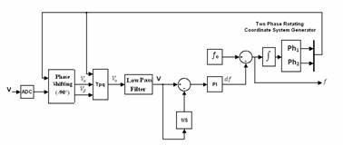
Figure 1. Block diagram of the PLL
The PLL proposed allows performing the measurement of the fundamental frequency of the input signal and the synchronization even in the presence of disturbances, both stationary and transient, thanks to the use of a coordinate transformation in the time domain and an innovative strategy for the evaluation of the phase error. Furthermore, it is proposed a new parameter to detect the presence of transient noise, so as to avoid analyzing the DFT with the portion of non-stationary signal.
Figure 2. Block diagram of the synchronizer
The PLL software developed is based on a technique developed in [6, 7], starting from the coordinate transformations of Park and Clarke.
Implementation and Characterization
The PLL
software has been implemented on
Results and Discussions
The tests conditions have been chosen according to the three tests states of the class A as recommended by the IEC 61000-4-30 norm [1], introducing on the entry signal the flicker, disturb of amplitude, harmonic and inter harmonic; especially for the trial condition 1, whereas the norm doesn't specify harmonic or inter harmonic order and amplitude, in particular, we kept those that are the nearest of the fundamental because they are the most harmful on the benefits of a synchronizer (2nd and 3rd harmonic and the inter harmonic to 1.1 f0).
In accordance with the norms [1] and [2] we verified that the synchronization error goes well in the limits (±0.03% f0, i.e. ±15mHz for f0=50Hz) in disturb presence foreseen by the test states; contrarily of the forecasts of [1] we took into account the transduction.
The tests have been done for five frequency values repartees in a uniform and linear manner in the interval (47.5-52.5 Hz, ±5% f0) [2].
On the tests set done, the proposed PLL displayed a synchronization error lower to the maximal limit foreseen by the norm [2] (limit equal to ±14mHz in the worse of the cases corresponds to ±0.03% of 47.5Hz); whereas on the contrary the PLL 4046 displayed a synchronization error superior to the limits know-indicated, in harmonic and inter harmonic presence (figure 3).
Figure 3. Synchronization error in steady-Experimental results
Figure 4. Characterization of the PLL in transition - Experimental results (1 = frequency, 2=difference f0(i)-f0(i-1), 3 = synchronisation error)
With regard to the tests done in transient disturbs presence, we took in consideration frequency variations in steps and in rails, in addition to the voltage entry phase and amplitude variations; the tests have been done with and without harmonic and inter harmonic, in conformity to the conditions of quoted tests in the norm [1].
The figure 4 regroups the results gotten with a frequency variation in steps of 47.5 HZ to 52.5 Hz, with the harmonic and inter harmonic presence on the entry signal .So that the difference of frequency f0 (i) - f0 (i-1) is more meaningful than the synchronization error for the transient disturbs existence identification .In fact the synchronization error is maintained in the limits during the transient, while it passes them when the transient is exhausted. As for the value of f0 (i) - f0 (i-1) this one varies in the same context that the transient.
We can put in evidence that: even in transient disturb presence, the PLL is very weakly sensitive to the harmonic and inter harmonic presence on the entry signal and that he is able to do the synchronization before the 200ms. Some analogous results have been gotten with other tests conditions [7].
From the constructive point of view, the electronic counters of reactive energy can be realized through an analog multiplier or numerical signals of current and voltage (the latter suitably phase-shifted by 90°). In the case of three-phase counters, two or three crews, to obtain the size of the reactive than active, you can take advantage of the properties of the star voltages and linked symmetric systems through artificial voltmeter connections. The measurement of the reactive power and therefore can also be made via the numerical implementation of the definition of reactive power. In this sense, it can be observed that, under distorted, the reactive power is not uniquely defined and in the bibliography there are several proposals [6]. In sinusoidal regime, the different types of construction work in accordance with the requirements of standards, while, in the presence of harmonic distortion, their operation is not known a priori.
In light of this, we conducted a study on the behavior of electronic meters in the presence of harmonic distortion; for this purpose, have been carried out comparisons in simulation and experimental tests on different types of counters, in the presence of harmonic distortion of voltage and current. In particular, here we report the results of tests carried out on a commercial electronic counter and other electronic virtual counters, implemented in the MATLAB environment, that implement the various methods of measuring the reactive energy; in particular, have been implemented a counter with a phase shift of a numerical quarter of a period of the voltage and a counter with phase shift through an integrator circuit. Through the use of a Fluke 6100A Electric Power Standard, introduced a known harmonic content of voltage and current, respectively, selected in accordance with IEC 50160 [9] and IEC 61000-3-2 [10]. The reading provided by the commercial counter, translated in terms of reactive power, was compared with the reactive power obtained using Fryze, Budeanu, Kusters-Moore, Shepherd-Zakikani, and Sharon (provided by the calibrator) and the reactive power measured by counters with a phase shift of a numerical quarter of a period of the voltage and phase shift through the integrator circuit (calculated in simulation).
The comparison was made by the percentage difference ∆Qj%=[(Qj-Qi)/Qi]·100 derived from the error percentage defined in [6], having Qj the reactive power measured in the various cases and Qi reactive power associated to the fundamental.
The choice of this parameter is motivated by the fact that the counters are designed to operate in the sinusoidal; in this sense, the DQj% is assumed as reactive power reference of the power associated to the fundamental that, practically, corresponds, in terms of energy, the measurement performed by the counter induction even in the presence of harmonic distortion. The choice of the parameter DQj% is, moreover, in line with the setting of the IEEE Standard 459-2000, which does not introduce an unambiguous definition of reactive power in the presence of harmonics, but separates the power components relating to the fundamental from the remaining components, due to harmonics.
The results obtained show that in the sinusoidal, as expected, the different counters lead to compatible results. Instead, in the scheme will have distorted values of very different for the different counters. Vice versa, the traditional counters induction, even in the presence of distortion, continues to measure practically the reactive energy associated with the fundamental [8]. For example, in Table 1 are reported some of the results obtained; in the table, the test conditions are summarized in terms of factors of total harmonic distortion refers to the phase shift between voltage and current ;j the angle voltage and current fundamental in the case of resistive-inductive load [8]; in cases b) and c) the different values of THDI are due to limitations on the current harmonics indicated in [10].
Analysis of the results shows that the commercial counter subjected to the tests measuring reactive energy very close to that measured by the counter that implements the definition of Fryze and their values of DQj% are high; vice versa, the values of relative to the counter with the integrator circuit and with the phase shift of a quarter of a period of the voltage are very small, so that these counters, even in the presence of harmonics, measure reactive energy closer to that associated with the fundamental, with a behavior very similar then to that of the counters induction.
Table 1. DQ % experimental results (IEC EN 50160 and 61000-3-2 Norms)
|
Test with harmonics impairs non multiple of 3 |
||||||||||
|
sinF |
THDv% |
THDi% |
DQcont% |
DQB% |
DQF% |
DQKM% |
DQSZ% |
DQSH% |
DQin% |
DQ90% |
|
1.00 |
7.90 |
13.90 |
+1.50 |
+0.20 |
+1.40 |
+0.50 |
+1.40 |
+1.40 |
0.00 |
0.00 |
|
0.50 |
+6.30 |
+0.20 |
+7.90 |
+0.50 |
+1.40 |
+1.40 |
0.00 |
0.00 |
||
|
0.25 |
+20.4 |
+3.30 |
+21.50 |
+1.10 |
+12.40 |
+12.40 |
0.00 |
0.00 |
||
|
Test with harmonics impairs multiples of 3 |
||||||||||
|
sinF |
THDv% |
THDi% |
DQcont% |
DQB% |
DQF% |
DQKM% |
DQSZ% |
DQSH% |
DQin% |
DQ90% |
|
1.00 |
5.30 |
6.60 |
+0.30 |
0.00 |
+0.40 |
+0.10 |
+0.10 |
+0.10 |
0.00 |
0.00 |
|
0.50 |
25.90 |
+10.80 |
-2.30 |
+12.40 |
-0.70 |
+11.10 |
+11.10 |
-0.40 |
+1.00 |
|
|
0.25 |
29.05 |
+56.00 |
-5.50 |
+61.30 |
-1.80 |
-48.30 |
-48.30 |
-0.90 |
+2.20 |
|
|
Test with harmonics pairs et impairs until 24 |
||||||||||
|
sinF |
THDv% |
THDi% |
DQcont% |
DQB% |
DQF% |
DQKM% |
DQSZ% |
DQSH% |
DQin% |
DQ90% |
|
1.00 |
7.90 |
17.30 |
+1.60 |
-0.30 |
+1.80 |
+0.20 |
+1.20 |
+1.20 |
0.00 |
-0.10 |
|
0.50 |
31.20 |
+14.7 |
+1.60 |
+15.90 |
+0.70 |
+5.50 |
+5.50 |
-0.30 |
+0.50 |
|
|
0.25 |
33.80 |
+53.50 |
-2.50 |
+59.80 |
-0.20 |
+20.6 |
+20.6 |
-0.60 |
+1.20 |
|
|
F: phase shift between voltage and current fundamental,
cont= electronic counter commercial, B=Budeanu, F=Fryze, KM=Kusters-Moore,
SZ=Shepherd- Zakikani, SH= |
||||||||||
The counter commercial subjected to experimental tests would seem, therefore, be based on the definition of reactive power of Fryze, although the manufacturer does not state anything in this sense; on the other hand, the use of this definition is without doubt a choice commercially and technically justifiable, given its ease of implementation. However, a counter thus produced, in the presence of harmonic pollution, reactive energy measurement appreciably higher than that measured by a counter with the integrator circuit and with a delay of one quarter of a period.
It is understandable, therefore, that the adoption of different counters may result in distorted regime, a different penalty of users, in terms of cost of energy, equal to the load conditions. Therefore, in the first place, manufacturers should be required to specify the principle according to which the counters are made, so as to be able to identify the size actually measured, in the presence of harmonic distortion; this mainly due to the absence of specific indications of a definition operational reactive energy at which conform to the realization of the counters themselves. Moreover, since the measurement made by the counters depending on their construction, it is considered necessary, in the regulatory framework, establish appropriate test conditions to characterize the performance counters under distorted. These tests, as well as under nominal reference, should also be carried out in conditions as possible representative of the conditions of actual operation, in which the measurement group may be at work. Moreover, when the measure is necessary to insert transducers of voltage and / or current, should be considered in the measurement chain (counter + transduction system), as well as the behavior of the transducers (usually CT and VT) can be influenced by the presence of harmonic disturbances of voltage and / or current.
Conclusion
It is believed, finally, that DQj% parameter could be used for this purpose, since it refers to the reactive power fundamental and which therefore allows to evaluate the performance of the meter compared to current legislation and current mode of penalization, which in fact do not consider the presence of distortion and make reference the sinusoidal case. On the other hand, in a broader sense, must be made in studies on the definition of parameters that enable a correct allocation of costs of the harmonics.
References
1. IEC 61000-4-30, Electromagnetic compatibility Testing and measurement Methods for measuring the quality of power, 2003.
2. IEC 61000-4-7, Electromagnetic compatibility Testing and measurement techniques, 2003.
3. IEC EN 62053-23, Apparatus for metering equipment (ac) Static meters for reactive energy (classes 2 and 3), 2003.
4. IEC 62052-11, metering of electricity tests and test conditions, 2003
5. IEEE Standard 1459-2000., IEEE Trial-use standard definitions for the measurement of electric power quantities: under sinusoidal, non-sinusoidal, balanced or unbalanced conditions, 2002.
6. Cosentino V., ., Nuccio S., Problems of measurement in electric power systems in the presence of harmonic distortion, XXVI Congress of the National Group of Electrical and Electronic Measurements Alta villa Milicia, 2009.
7. Cataliotti V. A., A New Strategy for Phase Locked Loop Power Quality Instruments Synchronization, Instrumentation and Measurements Technology Conference Ottawa, 2010.
8. Barbaro P., Behavior of reactive energy meters in polluted power systems, World Congress Metrology for a Sustainable Development Rio de Janeiro, 2011.
9. IEC 50160, Characteristics of the voltage supplied by public electricity distribution networks, 2000.
10. IEC 61000-3-2, Electromagnetic compatibility limits for harmonic current emissions, 2002.