Performance Characteristics and Double Revolving Theory of Single Phase Induction Motor
Yahaya Asizehi ENESI*
Department of Electrical and Electronics Engineering, Federal University of Technology, PMB 65, Minna, Nigeria.
E-mail: enesi.asizehi@futminna.edu.ng
Phone: 08035671462
Abstract
Single phase induction motors are used in number of applications such as in offices, homes and in factories. Their numerous applications and immense importance lead to the study of the general characteristics of such motors. In this paper the input data of a given single phase induction motor without core loss is obtained from laboratory and the motor equivalent circuit is developed from the input parameters and this circuit helps to obtain the principle of double revolving theory. Determination of the output parameters from input parameters using circuit equations lead to the plotting graphs of the motor performance characteristics for the purpose of illustration. The paper also demonstrates the simulation of the steady-state performance by MATLAB program.
Keywords
Equations; Equivalent circuit; Characteristics; Current; Motor; Rotor speed; Synchronous speed; Torque.
Introduction
A single phase induction motor exhibits a pulsating-in-time air gap field and a pulsating torque. In order to obtain a revolving air gap field and electromagnetic torque at a value exceeding zero, an auxiliary or starting winding is introduced [1]. The double revolving field concept is used for qualitative visualization and can be developed into quantitative theory that is applicable to variety of induction motor types. A given data of single phase induction motor is taken from laboratory and its equivalent circuit is obtained through the double revolving theory. Double revolving field theory is based on the fact that any pulsating quantity such as magnetic or electric quantity can be resolved into two parallel components that are opposite in directions. A magnetic flux having magnitude of Фm can be broken into two components each having magnitude of Фm/2 acting in opposite direction and each rotating at synchronous speed [2]. The resultant flux which is alternating in nature acts perpendicularly to the two component fluxes. This principle is based on the starting of single phase induction motor of which the alternating current supplies to the main winding of motor stator produces pulsating field that is divided into a forward and reverse or backward rotating field. These two fields or fluxes are equal in magnitude but opposite in directions. Each of the rotating fluxes or fields induces a voltage in the rotor that drives the current and produces torque which is equal in magnitude and opposite in direction so that each torque tries to turn the rotor in its own direction. Torque/rotor speed is used instead of the usual torque/synchronous speed characteristics on both forward and backward rotating magnetic field flux for better illustration of the two opposite pulsating quantities. The resultant torque is zero at starting and that is why a single phase induction motor is not self starting [3]. Since single phase induction motor requires the generation of the rotating magnetic field similar to that of three phase motor, this is achieved by converting the single phase supply into two phase supply through the use of additional winding known as starting winding to the main winding. The single phase induction motor can produce a rotating magnetic field by generating two currents which are out of phase using a capacitor. Resistance, capacitance or inductance when connected in series with the starting winding produces a phase shift which generates the starting torque, although capacitor is most frequently used in generating the starting torque [4]. A centrifugal switch is connected in series with the capacitor in series of starting winding which disconnects as the rotor speed reaches 75 percent or more to the operating speed of the motor.
Materials and Methods
A given input parameters of a single phase induction with core loss from laboratory is given below in Table 1.
Table 1. Input parameters
|
Symbol |
Quantity |
Input values |
|
V1 |
Phase voltage |
220V |
|
R1 |
Resistance of stator winding |
3.47Ω |
|
X1 |
Leakage reactance of stator winding |
4Ω |
|
R2 |
Rotor resistance referred to stator |
3.21Ω |
|
X2 |
Rotor reactance referred to stator |
4Ω |
|
Xm |
Magnetization reactance |
90Ω |
|
Nr |
Rotor speed |
2880rpm |
|
P |
Number of poles |
2 |
|
F |
Supply frequency |
50Hz |
|
Prot |
Rotational loss |
41.5watts |
Equivalent circuit and the mathematical Analysis
The equivalent circuit of single phase induction motor without core loss is shown in Figure 1. The single phase induction motor equivalent circuit with two imaginary rotor windings has a stator winding carrying the supply current that produces pulsating magnetomotive force which is stationary in space and varying in magnitude but alternating in time. One rotor rotates in forward direction which is the direction of rotating magnetic field with a slip s while the other rotates in backward direction in the opposite direction of the rotating magnetic field with the magnitude of slip whose value is the forward slip subtracted from two. Two torques are produced, one from each and the difference between the torques is the net torque acting on the rotor. The value of current, power and torque are calculated from the equations of the circuit [5 - 7].

Figure 1. Equivalent circuit of single phase induction motor without core loss
The slip of the forward flux is:
|
|
(1) |
The slip of the backward flux is:
|
|
(2) |
|
|
(3) |
|
|
(4) |
The stator impedance is expressed as:
|
|
(5) |
The impedance due to forward rotating field of the rotor is given as:
|
|
(6) |

The impedance of rotor due to backward field is given by:
|
|
(7) |

The total input impedance is given as:
|
|
(8) |
The supply or input current to the motor is:
|
|
(9) |
The power input of the motor is given as:
|
|
(10) |
The internal mechanical power or power converted into mechanical is:
|
|
(11) |
where Rf and Rb are real parts of Zf’ and Zb’
The output power of the motor or the shaft output power is:
|
|
(12) |
Torque acting on the shaft of the motor:
|
|
(13) |

The motor efficiency in percentage is given as:
|
|
(14) |
Voltage due to forward field rotor is given by:
|
|
(15) |
The current through forward rotor referred to stator is given by:
|
|
(16) |

The power input to forward field rotor is given as:
|
|
(17) |
Torque due forward rotating field of the rotor:
|
|
(18) |

Voltage due to backward field rotor:
|
|
(19) |
The current through backward rotor referred to stator is given as:
|
|
(20) |

The power input to backward field rotor is given as:
|
|
(21) |
Torque due backward rotating field of the rotor:
|
|
(22) |

Resultant torque acting on the motor:
|
|
(23) |
Resultant power acting on the motor or the net power input of the motor is given as:
|
|
(24) |
Results and Discussion
Table 2 shows the output values obtained from the given motor input data.
Figure 1 shows the efficiency-slip and power factor characteristics of single phase induction motor. The efficiency-slip curve shows that the slip the motor is 0.04 and the efficiency is 73 percent. The slip of a motor is the ratio of the difference between the synchronous speed and the rotor speed to the synchronous speed of the motor when the motor is considered under forward field. The value of slip is more than unity on the backward field. As the value of the slip increases to unity, the efficiency of the motor reduces on the forward field but on the backward field the slip begins to rise with the corresponding increase in the efficiency. When the slip is one there is negative efficiency and the motor does no work. At any corresponding points on the curve, the efficiency of the motor is the same. The efficiency of the motor is the same when the slip 0.8 and 1.2. The efficiency-power factor curve shows that the efficiency of the motor increases with corresponding increase in power factor. The power factor of the motor is 0.70 when the efficiency of the motor is 73 percent.
Table 2. Output parameters
|
Slip (s) |
Pf |
Pin |
Pconv |
Pout |
Efficiency (%) |
|
0 |
0 |
0 |
0 |
0 |
0 |
|
0.02 |
0.49 |
523.64 |
402.94 |
425.27 |
81.21 |
|
0.04 |
0.70 |
930.35 |
718.73 |
677.23 |
72.8 |
|
0.06 |
0.78 |
1286.6 |
944.40 |
902.90 |
70.18 |
|
0.08 |
0.81 |
1593.4 |
1094.8 |
1053.3 |
66.10 |
|
0.10 |
0.82 |
1849.7 |
1184.9 |
1143.4 |
61.82 |
|
0.15 |
0.81 |
2315.9 |
1234.7 |
1193.2 |
51.2 |
|
0.2 |
0.78 |
2598.2 |
1151.9 |
1110.4 |
42.74 |
|
0.40 |
0.70 |
2965.3 |
605.09 |
563.60 |
19.0 |
|
0.60 |
0.66 |
2996.70 |
240.24 |
198.74 |
6.63 |
|
0.80 |
0.64 |
2988.8 |
55.84 |
14.34 |
0.48 |
|
1.0 |
0.63 |
2984 |
0 |
-41.5 |
-1.39 |
|
1.20 |
0.64 |
2989.1 |
55.84 |
14.34 |
0.48 |
|
1.40 |
0.66 |
2998 |
240.24 |
198.74 |
6.63 |
|
1.60 |
0.70 |
2964.1 |
605.09 |
563.6 |
19 |
|
1.80 |
0.78 |
2598.2 |
1148.2 |
1106.7 |
42.60 |
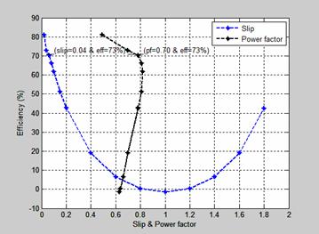
Figure 1. Efficiency-slip & power factor characteristics of single phase induction motor
Figure 2 shows the power-slip characteristic of a single phase induction motor. The input power gradually increases with corresponding increase in the slip until it gets to its maximum operating characteristic. The difference between the power output and the mechanical power converter is the rotational loss due to electrical and mechanical losses. At standstill, the input power, the mechanical power converter and the power output is zero. The slip of the motor is 0.04 with input power of 930.35 watts and the output power developed is 677 23 watts.
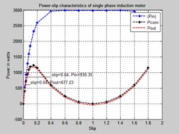
Figure 2. The power-slip characteristics of single phase induction motor.
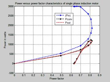
Figure 3. Power-power factor characteristics of single phase induction motor
The power-efficiency characteristic of single phase induction motor is shown in Figure 4. The efficiency of a motor is a measure of its effectiveness with which it converts electrical energy input into mechanical energy output as it drives a load. The difference between the power input and the power output comprises the mechanical and electrical losses known as the rotational losses. Motors of higher power input ratings generally correspond to lower efficiency ratings while those of lower horsepower ratings are of higher operating efficiency. Smaller input power rating single phase motor is preferable to the bigger ratings because its efficiency is more than the higher rating motor. The efficiency of this motor is 73 percent as its input power rating is 930.35 watts and the output power is 677.23 watts. The maximum operational performance of the motor is when the efficiency of the motor is 81 percent at slip of 0.02.
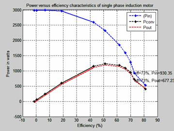
Figure 4. Power-efficiency characteristics of single phase induction motor
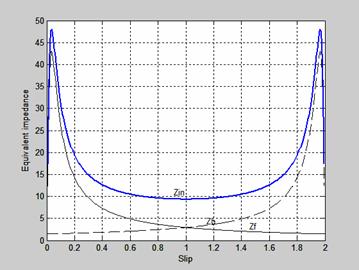
Figure 5. Impedance-slip characteristics of single phase induction motor
Figure 5 is the Impedance-slip characteristics of single phase induction motor. The slip of both forward and backward flux impedance are equal when the slip is one. The resultant of both impedances is the algebraic sum of the impedance which is represented as Zin.
Figure 6 shows the torque-slip characteristics of the forward and backward torque produced when a single phase supply is given only to the main winding of the single phase induction motor. The forward and backward fields do not remain constant in the air gap but alternate in opposite direction. The slip of both fields is one at standstill. At standstill, the forward and backward torques is equal and opposite and the net torque is developed (resultant torque). The slip of the forward torque Sf is less than unity while that of the backward torque is 2-Sf. The resistance/reactance ratios of usual rotor of forward torque at slips less than unity are greater than that of the backward torque whose slips are more than unity and this makes the resultant torque to be in the direction of rotation of the forward magnetic flux.
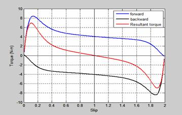
Figure 6. Torque-slip characteristics of rotor at standstill
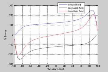
Figure 7. Torque-rotor speed characteristic of single phase induction motor
Figure 7 is the torque-rotor speed characteristic of single phase induction motor. As the speed increases, positive forward torque increases and backward torque decreases, less negative and vice versa. At zero speed, the forward is equal to backward torque and gives zero resultant torque.
The power input to both forward and backward field rotor-slip characteristics of single phase induction motor is shown in Figure 8. The power input to forward field rotor acts in the direction opposite to the backward. The slip of both fields is one at standstill. At standstill, the forward and backward torque is equal and opposite. This characteristic is similar to that of torque-slip characteristic shown in Figure 6. The mechanical converter is zero when the slip is one.
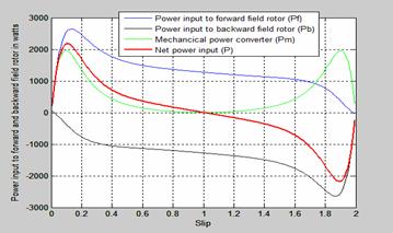
Figure 8. Power input to both forward and backward field rotor-slip characteristics
Conclusion
The double revolving field theory is used to develop the equivalent circuit of single phase induction motor. Two fields are determined and the torque produced by each field is obtained. The difference between the forward and the backward torque is the net torque acting on the rotor. The characteristics of power input and power output in relation to the power factor, efficiency, slip are investigated for the purpose of illustration and it is found that lower horsepower rating of single phase induction motors have higher efficiency and higher power factor than those of the higher rating horsepower motors.
References
1. Popescue M., Analytical Prediction of electromagnetic torque in single phase and two phase of AC motors, Helsinki University of Technology, laboratory of Electromechanics. Helsinki, 2004, Report 73.
2. Theraja B. L, A Textbook of Electrical Technology, p. 1367-1977. S.Chand & Company Ltd.7361, Ram Nagar, 2003, New Delhi-110 055, India.
3. Rakesh P. AC Induction Motor Fundamentals. AN887, Microchip Technology Inc. 2003, pp. 3-6.
4. Storey J. How real electric motors work, University of New South Wales, Syndney, Auatralia, 2011.
5. McGraw-H, Revolving Theory of Single Phase Induction Motor, McGraw-Hill Companies, 2003, p. 467-469. Retrieved from www.knovel.com
6. Sen P. C, Principles of Electric Machines and Power Electronics, 2nd edition, 1997, John Wiley and Sons Inc, New York. p. 373-392
7. Agarwal R. K. Principle of Electrical Machine Design, 4th edition, p.366-381. S.K.Kataria & Sons, 4424/6, Guru Nanak Market,2000, Nai Sarak, Delhi, India.