Study of UPFC Optimal Location Considering Loss Reduction and Improvement of Voltage Stability and Power Flow
Islam Youcef DJILANI KOBIBI*, Samir HADJERI, and Mohammed Abdeldjalil DJEHAF
Intelligent Control and Electrical Power System Laboratory,
Djillali Liabes University of Sidi Bel-Abbes, ALGERIA
E-mails: youcef_kobibi@yahoo.fr; shadjeri2@yahoo.fr; med_djehaf@yahoo.fr
* Corresponding author: +213670104148
Abstract
With the increase in power demand, operation and planning of large interconnected power system are becoming more complex, so power system will become less secure and stable. A new concept of Flexible AC Transmission system (FACTS) brought radical changes in the power system operation and control. FACTS controllers narrow the gap between the no controlled and the controlled power system mode of operation, by providing additional degrees of freedom to control power flows and voltages. Unified Power Flow Controller (UPFC) is a versatile FACTS device which can independently or simultaneously control the active power, the reactive power, and the bus voltage to which it is connected. The main purpose of this paper is to identify the optimal location of the Unified Power Flow Controller (UPFC) in order to minimize active power losses and improve the voltage profiles using the injection model of the (UPFC) in Newton-Raphson load flow algorithm, in an IEEE- 14, 30, 57, 118, 300 Bus test systems.
Keywords
FACTS (Flexible AC Transmission System); Power Flow Control; UPFC (Unified Power Flow Controller); Newton- Raphson; Optimized Placement.
Introduction
Electricity market activities and a growing demand for electricity have led to heavily stressed power systems. This requires operation of the networks closer to their stability limits. Power system operation is affected by stability related problems, leading to unpredictable system behavior.
Nowadays, several important issues related to power system have been discussed worldwide. Some of the serious issues are the power quality, transmission loadability, congestion management; reduce power losses and voltage stability. [1]
Most large power system blackouts, which occurred worldwide over the last twenty years, are caused by heavily stressed system with large amount of real and reactive power demand and low voltage condition. When the voltages at the system buses are low, the losses will also be increased. [2]
To overcome these issues, best approach is using FACTS devices.
In the late 1980s the Electric Power Research Institute (EPRI) has presented a new technology known as FACTS. [1]
Flexible AC Transmission Systems (FACTS) are alternating current transmission systems incorporating power electronic-based and other static controllers to enhance controllability and increase power transfer capability. The rapid development of the power electronics industry has made FACTS devices increasingly attractive for utility deployment due to their flexibility and ability to effectively control power system dynamics.
Unified power flow controller (UPFC) is the most comprehensive multivariable flexible AC transmission system (FACTS) controller. Simultaneous control of multiple power system variables with UPFC posses enormous difficulties.
Many advantages in power system include UPFC such as minimization of system losses, elimination of line over loads and low voltage profiles. [3]
In this paper, the selection of the best possible location for installation of UPFC is carried out with an objective of reducing the losses and improving the voltage profile using a mathematical model for UPFC which will be referred as UPFC injection model. This model is helpful to understand the impact of the UPFC on power system. Furthermore, the UPFC injection model can easily be incorporated in the Newton-Raphson power flow algorithm.
Compared to previous studies on the UPFC optimal location based on minimizing power losses and enhancing voltage profile, this work consider also the improvement of power flow and present a clear study by incorporating the UPFC injection model on small medium and large power system, and present a better loss reduction, and optimal setting for the UPFC. The previous studies are [1], [2] and [8] used the IEEE 14, 30, 57 Bus test systems, this work include larger test systems (IEEE 118, 300 Bus test systems).
Material and Method
Power Flow Control
Conventionally, the power flow (real power P and reactive power Q) on the transmission line can be controlled by adjusting the parameters of the transmission lines (line reactance X, sender voltage Vs and receiver Vr, and phase angle), corresponding power transfer equation as follows:
|
|
(1) |
|
|
(2) |
Control by conventional means can only be done separately (not simultaneously). With the rapid advancement of semiconductor technology, control of power flow on the transmission line can be carried out simultaneously or separately, with the Unified Power flow controller (UPFC). [4]
Basic Structure of UPFC
The UPFC is the most versatile and complex of the FACTS devices, combining the features of the STATCOM (Static Synchronous Compensators) and the SSSC (Static Synchronous series compensators). The main reasons behind the wide spreads of UPFC are: its ability to pass the real power flow bi-directionally, maintaining well regulated DC voltage, workability in the wide range of operating conditions etc. The basic components of the UPFC are two voltage source converters (VSCs) sharing a common DC storage capacitor, and connected to the power system through coupling transformers.
One VSC is connected to in shunt to the transmission system via a shunt transformer, while the other one is connected in series through a series transformer. The DC terminals of the two VSCs are coupled and this creates a path for active power exchange between the converters. Thus the active supplied to the line by the series converter can be supplied by the shunt converter as shown in figure 1. [5]
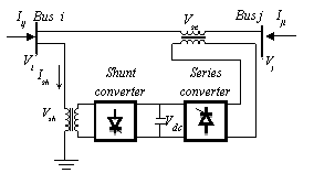
Figure 1. UPFC model
The series converter is controlled to inject a symmetrical three phase voltage system (Vse), of controllable magnitude and phase angle in series with the line to control active and reactive power flows on the transmission line. So, this converter will exchange active and reactive power with the line. The reactive power is electronically provided by the series converter, and the active power is transmitted to the DC terminals. The shunt converter is operated in such a way as to demand this DC terminal power (positive or negative) from the line keeping the voltage across the storage capacitor Vdc constant. So, the net real power absorbed from the line by the UPFC is equal only to the losses of the converters and their transformers. The remaining capacity of the shunt converter can be used to exchange reactive power with the line so to provide a voltage regulation at the connection point. The two VSCs can work independently of each other by separating the DC side. So in that case, the shunt converter is operating as a STATCOM that generates or absorbs reactive power to regulate the voltage magnitude at the connection point. Instead, the series converter is operating as SSSC that generates or absorbs reactive power to regulate the current flow, and hence the power flows on the transmission line.
UPFC Injection Model for Power Flow Studies
A UPFC can be represented by two voltage sources representing fundamental components of output voltage waveforms of the two converters and impedances being leakage reactance's of the two coupling transformers. Figure 2 depicts two voltage-source model of UPFC. System voltage is taken as reference vector Vi = Vi < 0° and Vi = Vse +Vi.
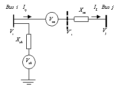

Figure 2. Voltage-source model of UPFC
Voltages sources Vsh and Vse are controllable in both their magnitudes and phase angles, r and γ are respectively the p.u. magnitude and phase angle of series voltage source, operating within the following specified limits given by:
|
|
(3) |
Vse should be defined as:
|
|
(4) |
The model is developed by replacing voltage source Vse by a current source Ise parallel with the transmission line as shown in figure 3, where bse=1/Xse.
|
|
(5) |
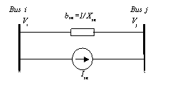
Figure 3. Replacement of series voltage source by current source
The current source Ise can be modeled by injection powers at the two auxiliary buses i and j.
|
|
(6) |
|
|
(7) |
Injected powers Sis and Sjs can be simplified according to the following operations by substituting (4) and (5) into (6).
|
|
(8) |
By using Euler Identity, (ejγ =cos γ +j sin γ) (8) takes the form of:
|
|
(9) |
|
|
(10) |
By using trigonometric identities, (10) reduces to:
|
|
(11) |
(11) can be decomposed into its real and imaginary components,
|
|
(12) |
where
|
|
(13) |
|
|
(14) |
Similar modifications can be applied to (7); final equation takes the form of,
|
|
(15) |
(12) can also be decomposed into its real and imaginary parts.
|
|
(16) |
where
|
|
(17) |
|
|
(18) |
Based on (13), (14), (17), and (18), power injection model of the series-connected voltage source can be seen as two dependent power injections at auxiliary buses i and j as shown in figure 4. In UPFC, shunt branch is used mainly to provide both the real power Pseries, which is injected to the system through the series branch, and the total losses within the UPFC. The total switching losses of the two converters is estimated to be about 2% of the power transferred for thyristor based PWM converters. [6]

Figure 4. Equivalent power injection of series branch
If the losses are to be included in the real power injection of the shunt-connected voltage source at bus i, Pshunt is equal to 1.02 times the injected series real power Pseries through the series-connected voltage source to the system.
|
|
(19) |
The apparent power supplied by the series converter is calculated as:
|
|
(20) |

Active and reactive power supplied by the series converter can be calculated from (20).
|
|
(21) |
|
|
(22) |
|
|
(23) |
|
|
(24) |


Final form (20) takes the form of
|
|
(25) |
where:
|
|
(26) |
|
|
(27) |
The reactive power delivered or absorbed by converter 1 is not considered in this model, but its effect can be modeled as a separate controllable shunt reactive source. In this case main function of reactive power is to maintain the voltage level at bus i within acceptable limits. In view of the above explanations, Qshunt can be assumed to be 0. Consequently, UPFC mathematical model is constructed from the series-connected voltage source model with the addition of a power injection equivalent to Pshunt+ j0 to bus i, as depicted in figure 5. Finally, UPFC mathematical model can be constructed by combining the series and shunt power injections at both bus i and bus j as shown in figure 6. The elements of equivalent power injections in figure are, [7]
|
|
(28) |
|
|
(29) |
|
|
(30) |
|
|
(31) |

Figure 5. Equivalent power injection of shunt branch

Figure 6. UPFC mathematical model
Incorporating UPFC Injection Model for Load Flow Studies
The UPFC injection model can easily be incorporated in a load flow program. If a UPFC is located between node i and node j in a power system, the admittance matrix is modified by adding a reactance equivalent to XS, between node i and node j. The Jacobian matrix is modified by addition of appropriate injection powers. If we consider the linearized load flow model as: [8]
|
|
(32) |
where H, N, J, L are the elements of Jacobian matrix,[9]
|
|
(33) |
From the mathematical modeling point of view, the set of nonlinear, algebraic equations that describe the electrical power network under the steady state conditions are solved for the power flow solutions. Over the years, several approaches have been put forward to solve for the power flow equations. Early approaches were based on the loop equations and methods using Gauss-type solutions. This method was laborious because the network loops has to be specified by hand by the systems engineer. The drawback of these algorithms is that they exhibit poor convergence characteristics when applied to the solution of the networks. To overcome such limitations, the Newton-Raphson method and derived formulations were developed in the early 1970s and since then it became firmly established throughout the power system industry. In the project a Newton Raphson power flow algorithm is used to solve for the power flow problem in a transmission line with UPFC. Figure 7 shows the flow chart of the used algorithm. [10]
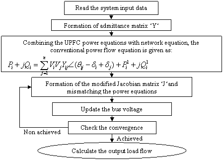
Figure 7. Flow chart of the algorithm [11]
Simulation studies were done for IEEE 14-, 30-, and 118- bus systems, data of the 14-bus system contains 20 lines, 5 generators, and Data of the 30-bus system contains 41 lines, 6 generators, and Data of the 57-bus system contains 80 lines, 7 generators, and Data of the 118-bus system contains 186 lines, 54 generators, Data of the 300-bus system that contains 295 lines, 69 generators are taken from [12]. In this work, UPFC is situated in every possible line and the best location is determined considering the minimum active power loss and the profile of the voltage and the active power flow through the lines.
Results and Discussion
The active power losses are shown in figure 8, the voltage magnitude and the active power flow are shown in figure 9, and figure 10, respectively, for IEEE 14-bus test system.
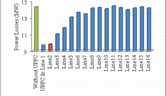
Figure 8. Active Power Losses without UPFC and With UPFC in different lines
For the IEEE 14-bus test system the location that presents the lowest power losses is to connect the UPFC in line 1. As shown in figure 8, but the best voltage profile was obtained when the UPFC is connected to line 2, between buses 1 and 5, the total active power losses get decreased from 14.31 MW to 9.83 MW, with 31% losses reduction
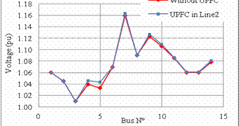
Figure 9. Voltage profile without UPFC and with UPFC in the optimal location
Also the voltage gets improved as shown in figure 9, the voltage profile gets a higher level with placing the UPFC.
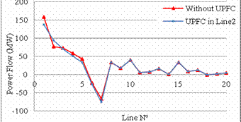
Figure 10. Power flow without UPFC and with UPFC in the optimal location
From figure 10, it can be observed that the active power flow in lines changes by incorporating the UPFC, the Lines 1,3,4,5,6,7 were relieved by increasing the load flow in Line 2, which represent an improvement of the load flow.
The active power losses, the voltage magnitude and the active power flow are shown in figure 11, figure 12, figure 13, respectively, for IEEE 30-bus test system.
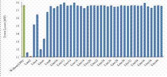
Figure 11. Active Power Losses without UPFC and With UPFC in different lines
For the IEEE 30-bus test system, when the UPFC is placed in line 2 between buses 1 and 3, the total active power losses get decreased from 17.55 MW to 11.05 MW, with 33% losses reduction, as shown in figure 11, and from the figure 12, it can be seen that the voltage profile is improved after incorporating the UPFC, and figure 13, represent an improvement of power flow, the UPFC relieve many lines within its region as line 1,2,3,5,6,8 by increasing the power flow through the lines 4,7,9.
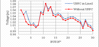
Figure 12. Voltage profile without UPFC and with UPFC in the optimal location
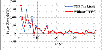
Figure 13. Power flow without UPFC and with UPFC in the optimal location
The active power losses, the voltage magnitude and the active power flow are shown in figure 14, figure 15, figure 16, respectively, for IEEE 57-bus test system.
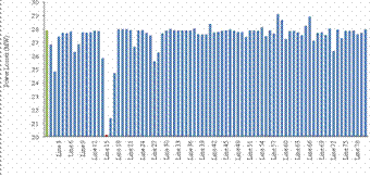
Figure 14. Active Power Losses without UPFC and With UPFC in different lines
For IEEE 57-bus test system we observe the same effect of the UPFC on the test system, the optimal location which is to install UPFC in line 15 between buses 1 and 15 present the lowest active losses, the UPFC decrease the losses from 27.86 MW to 20.08 MW, with 27% losses reduction as shown in figure 14, and present a higher voltage profile as shown in figure 15, and an improved power flow by relieving most of the overloaded lines such as line 1,2,3,4 by enhancing the active power flow in under loaded lines such as line 15 as shown in figure 16.
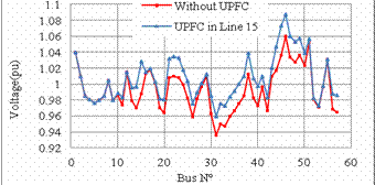
Figure 15. Voltage profile without UPFC and with UPFC in the optimal location
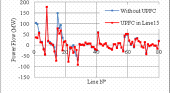
Figure 16. Power flow without UPFC and with UPFC in the optimal location
The active power losses and the profile of the voltage and active power flow are shown in figure 17, figure 18, figure 19, respectively, for IEEE 118-bus test system.
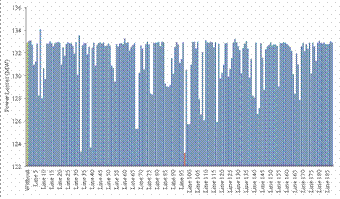
Figure 17. Active Power Losses without UPFC and With UPFC in different lines
For IEEE 118-bus test system, we can see clearly that the power loss decrease by installing the UPFC in its optimal location in line 97 between buses 64 and 65 from 132.86 MW to 123.13 MW with 7.23% of losses reduction, as shown in figure 17 and from figure 18, its can be seen that the voltage profile is improved by introducing the UPFC and from figure 19, we can see that the power flow also was improved by the UPFC by relieving the lines in the area where the UPFC was installed.
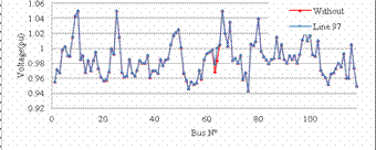
Figure 18. Voltage profile without UPFC and with UPFC in the optimal location
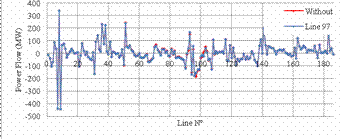
Figure 19. Power flow without UPFC and with UPFC in the optimal location
The active power losses and the profile of the voltage and active power flow are shown in figure 20, figure 21, figure 22, respectively, for IEEE 300-bus test system.
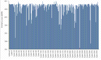
Figure 20. Active Power Losses without UPFC and With UPFC in different lines
For IEEE 300-bus test system, the UPFC also decrease the active power losses as shown in figure 20, from 409 MW to 381.82 MW when it is installed on its optimal location on line 232 between buses 192 and 225, with 6.41% of losses reduction, and figure 21, shows an improvement of voltage profile in the area where the UPFC was installed, and figure 22, shows an improvement on power flow where some lines were relieved such as line 268 and others enhancing the power flow of other lines such as line 232.
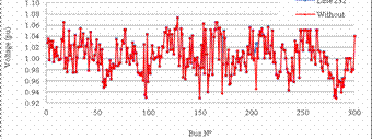
Figure 21. Voltage profile without UPFC and with UPFC in the optimal location
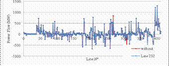
Figure 22. Power flow without UPFC and with UPFC in the optimal location
This paper present a clear study of UPFC optimal location based on minimizing the power system losses and improving the voltage profile and the power flow in the transmission lines, the simulation was tested on various test system, all the possible cases were examined using a MATLAB program based on Newton-Raphson Algorithm. Compared to [1, 2] and [8] this paper present a higher loss reduction, and a better improvement of power flow.
Conclusions
The simulations results shows that the UPFC changes the configuration of the power system in any location, but the optimal location present the best benefit on power losses and voltage magnitude, the effect of the UPFC is very remarkable on the small system compared to large power system such as IEEE-118 and 300 bus test system.
UPFC device can adjust the distribution the system power flow among the transmission lines and decrease the system losses and improve the voltage profile to provide more stability.
References
1. Ahmadnia S., Boroomand N., Tous S. I., Hasanpour S., New Modeling of UPFC for Power Flow Study and Setting Parameters to Increase Voltage Level and Reduce Power Losses, International Journal of Automation and Power Engineering, 2012, 01, p.77-82.
2. Ramesh P., Reddy M.D., Loss Reduction Through Optimal Placement of Unified Power-Flow Controller using Firefly Algorithm, International Journal of Advanced Research in Electrical, Electronics and Instrumentation Engineering, 2013, 2(10), p. 4657-4667.
3. Venkateswarlu K., Saibabu Ch., A New Evalutionary Algorithms Used For Optimal Location of UPFC on Power System, Journal of Theoretical and Applied Information Technology, 2010, 21(20), p. 107-118.
4. Jaya I., Harun N., Tola M., dan Tjaronge W., Improvement of Power Losses On Transmission Line Using Unified Power Flow Controller (UPFC) For Street Lighting Requirement, Research Journal of Science and IT Management, 2013, 2(9), p. 19-27.
5. Bhowmik A.R., Nandi C., Implementation of Unified Power Flow Controller (UPFC) for Power Quality Improvement in IEEE 14-Bus System, International Journal of Computer Technology and Applications, 2011, 2(6), p. 1889-1896.
6. Behshad M., Lashkarara A., Rahmani A.H., Optimal Location of UPFC Device Considering System Loadability, Total Fuel Cost, Power losses and Cost of Installation, 24th International Power System Conference, 2009.
7. Chengaiah C., Marutheswar G.V., Satyanarayana R.V.S., Control Setting Of Unified Power Flow Controller Through Load Flow Calculation, Asian Research Publishing Network, Journal of Engineering and Applied Sciences, 2008, 3(6), p. 6-10.
8. John T., Line Loss Minimization and Voltage Regulation using UPFC, Elixir International Journal, 2011, 38, p. 4222-4224.
9. Kumar P.P., Poornachandrarao N., Improvement of Power Flow in the Power System Network by using UPFC Device, International Journal of Engineering Research and Applications, 2012, 2(3), p. 1194-1199.
10. Sunil Kumar A.V., Roopa V., Akthar J., Shivasharanappa G.C., Transmission Loss Allocation and Loss Minimization By Incorporating UPFC in LFA, International Journal of Modern Engineering Research, 2011, 1(1), p. 236-245.
11. Pandita A., Jain S.K., A Review on Power Flow Analysis with UPFC and its Applicability, International Journal of Engineering Research & Technology, 2013, 2(6), URL: http://www.ijert.org/view.php?id=3995&title=a-review-on-power-flow-analysis-with-upfc-and-its-applicability.
12. Power Systems Test Case Archive, University of Washington, 2003. Available at: www.ee.washington.edu/research/pstca.