Analysis of non-salient pole synchronous generator using phasor diagrams
Yahaya Asizehi ENESI*, Adamu Murtala ZUNGERU, Isah Agbogunde ADEMOH
Department of Electrical and Electronics Engineering, Federal University of Technology, PMB 65, Minna, Niger state, Nigeria
E-mails: enesi.asizehi@futminna.edu.ng*; adamuzugeru@ieee.org; adagisah@yahoo.com
*Phone: 08035671462; 08034031227; 08065491517
Abstract
In this paper, various performance equations are derived from phasor diagrams of a three phase non-salient pole (cylindrical rotor) synchronous generator of known armature resistance and of ignored armature resistance for lagging, unity and leading power factor load. These equations are used to calculate the output parameters of non-synchronous generator and to plot the graphs of terminal voltage-armature current, torque angle-armature current, torque angle-terminal voltage, power-torque angle and torque-speed characteristics through simulation by MATLAB program for the purpose of illustration.
Keywords
Armature resistance; Lagging power factor; Leading power factor; Non-salient pole synchronous generator; Phasor diagrams; Unity power factor
Introduction
The increase in the demand and the applications of synchronous generator for domestic and industries due to high rate of power consumption becomes necessary for the researchers and engineers to study synchronous generator characteristics. The input data of a non-salient pole synchronous generator is given to determine the generator characteristics using various theories and equations derived from possible phasor diagrams of the generator operating on leading, unity and lagging power factor load on for the purpose of presentation.
The use of MATLAB for simulation helps to achieve the desired result. A DC generator is applied to the rotor or field winding which produces the main flux and this flux induces an electromotive force in the armature winding and the armature current is established depending on the load condition of that synchronous generator. The magnetic flux of the rotor produces a rotor magnetic field. The rotor is then driven at constant speed by an external means (turbine) to produce a rotating magnetic field which induces a three-phase voltage in the stator [1]. The rotating field flux induces voltage in stator (armature) winding whose frequency depends on the speed [2]. DC excitation is important for the stability of the terminal voltage and also to respond to sudden load changes [3]. Synchronous generator converts mechanical power into electrical power. The sources of mechanical power are the prime movers such as diesel engine, steam turbine, water turbine and any similar device [4]. For high speed generators (non-salient pole or cylindrical rotors), the prime over are usually steam turbines using fossil and nuclear energy resources while that of low speed (salient pole rotors) are often driven by hydro-turbines that use water power for generation. The smaller synchronous generators for private generation and for standby units use diesel engines or gas turbines as prime movers [5]. When synchronous generator is connected to a load, current flows through the armature. This current causes an armature or stator flux to be created which tends to counteract the air gap flux that is produced by field excitation. Air gap flux is reduced which causes the corresponding reduction in the terminal voltage. If the rotor excitation current is increased, the terminal voltage can be restored. This demagnetizing effect of the armature current which results in the reduction of flux in the air gap is known as armature reaction and can be compensated by increasing the field excitation current [6]. Synchronous generators are classified into rotating field type and rotating armature type according to the arrangement of the field and armature windings. Synchronous generator with uniform air gap is known as the non-salient generator while that of non-uniform air gap is known as the salient pole generator [7, 8].
The research is aimed at obtaining the possible output characteristics of a non-salient pole synchronous generator which is excited as load is connected to it. This is achieved when derived equations from various phasor diagrams of power factor loads are investigated through MATLAB program and the results presented for the purpose of visualization.
Material and method
The input parameters are shown in Table 1.
Table 1. Input parameters
|
Quantity (abb) – Units of measurement |
Input values |
|
Frequency (f) |
50 |
|
Number of poles (P) |
2 |
|
Apparent power (S) - KVA |
1800 |
|
Line voltage (VL) - V |
13500 |
|
Armature resistance (Ra) - ohms |
1.5 |
|
Synchronous reactance (Xs) - ohms |
32 |
|
Load power in watts (Kw) - KW |
1300 |
|
Power factor (Pf) |
0.8 |
The effective generated voltage per phase is the sum of the no load voltage and the armature reaction emf.
|
|
(1) |
where Eegp = effective generated voltage per phase, VT = Terminal voltage per phase, Ra = Armature resistance per phase, Xa = Armature reactance per phase, The armature reaction induced voltage per phase is given by:
|
|
(2) |
where Ia is the armature current per phase
The synchronous reactance per phase is given by:
|
|
(3) |
where Xm = magnetization reactance per phase or armature reactance per phase
The no-load induced electromotive force is given as:
|
|
(4) |
The synchronous impedance is given by:
|
|
(5) |
Figure 1(a) is the equivalent circuit of the non-salient pole synchronous generator while that of 1(b) is the stator and the cylindrical rotor of the non-salient pole of the synchronous generator. The stator of the non-salient pole synchronous generator is usually star-connected.
Figure 1. Equivalent circuit, stator and rotor of non-salient pole synchronous rotor
Figure 1, 2, 3, 4, 5, 6, 7 and 8 are obtained from [9, 10].
Figure 1 above is the Equivalent circuit, stator and rotor of non-salient pole synchronous rotor.
Lagging factor
Figure 2 shows the
phasor diagram of lagging power factor load with IaRa inclined downward
at angle ![]() to the horizontal. Using
Pythagorean Theorem:
to the horizontal. Using
Pythagorean Theorem:
![]() and substituting the
corresponding values for the letters to
and substituting the
corresponding values for the letters to
obtain ![]()
where Vt is the terminal
voltage per phase, Ia is the armature current per phase, Ra is
the armature resistance per phase, δ = torque angle, power angle or
load angle and ![]() = angle between no – load induced emf
per phae and the ter min al voltage per phase
= angle between no – load induced emf
per phae and the ter min al voltage per phase

Figure.
2. Phasor diagram of lagging power factor with IaRa
inclined downward at an angle ![]()
The no-load voltage per phase is given by:
|
|
(6) |
|
|
(7) |
For voltage regulation,
the angle of Vt is first considered to be zero so that the imaginary
part of ![]() becomes
becomes ![]() The
angle θ is negative for lagging power factor (current is lagging). The
terminal voltage per phase can now be expressed as
The
angle θ is negative for lagging power factor (current is lagging). The
terminal voltage per phase can now be expressed as![]() .
.

Figure 3. Phasor diagram of lagging power factor with Ra=0
In Figure 3, the
armature is too small and it is ignored so that Ra = 0. In triangle
OABO, ![]() . Substituting the corresponding values
and we obtain:
. Substituting the corresponding values
and we obtain:
|
|
(8) |

Figure 4. Phasor diagram of lagging power factor with IaRa lying horizontally (not inclined)
Figure 4 shows the phasor diagram of lagging power factor load in which IaRa lies horizontally.
From triangle OAD, ![]()
|
|
(9) |
Unity power factor
From triangle OAC in
Figure 5, ![]()
|
|
(10) |

Figure 5. Phasor diagram of unity power factor
Leading factor
The phasor diagram of
leading power factor with IaRa inclined upward at an angle ![]() is
shown in figure 6 and from triangle OAD,
is
shown in figure 6 and from triangle OAD, ![]() and by
Pythagorean Theorem,
and by
Pythagorean Theorem, ![]() . Substituting the corresponding value
to obtain
. Substituting the corresponding value
to obtain![]()
|
|
(11) |
|
|
(12) |

Figure 6. Phasor diagram of
leading power factor with IaRa inclined upward at an angle ![]()
The value of armature
resistance is ignored because the value very small compared to synchronous
reactance. The phasor diagram of leading power factor with armature resistance Ra
ignored is shown in Figure 7. From triangle OABCO,![]() ,
, ![]() ,
then
,
then ![]()
|
|
(13) |

Figure 7. Phasor diagram of leading power factor without Ra
Figure 8 shows the
phasor diagram of leading power factor with IaRa lying horizontally.
From triangle, ![]() so that
so that ![]()
|
|
(14) |

Figure 8. Phasor diagram of leading power factor with IaRa lying horizontally
General Equation of Non-Salient Pole Synchronous Generator
The general voltage equation of synchronous generator is given by:
|
|
(15) |
The voltage equation for synchronous generator with pure resistive load (unity power factor) is given by:
|
|
(16) |
The voltage equation for synchronous generator with inductive load (lagging power factor) is given by:
|
|
(17) |
The voltage equation for synchronous generator with capacitive load (leading power factor) is given by:
|
|
(18) |
The armature current of synchronous generator is given by:
|
|
(19) |
where Vt = Vt < 0, Eo = Eo < δ and Zs = Zs < θ.
![]()
![]()
![]()
![]()
![]()
![]()
![]()
Power equation
The apparent power of a star-connected synchronous generator is given by:
|
|
(20) |
The per-phase complex power output at the terminal is given as:
|
|
(21) |
The conjugate of the current phasor Ia shows that the lagging reactive power is considered positive while that of the leading reactive power is considered negative. The reference phasor is the constant bus voltage per phase which is Vt. The quantities inside the vertical bars represent the magnitudes of the phasors.
![]()
![]()
![]()
The conjugate of the current phasor Ia is given by:
|
|
(22) |


Substitute this value into equation (22):
|
|
(23) |
The real and reactive powers are expressed respectively as P and Q:
|
|
(24) |
|
|
(25) |
Ra is too small and can be neglected,
so that Zs = Xs and when θS = 90°. The active
power flows due to the phase difference between the Eo and Vt.
The voltage drop of the reactance between Eo and Vt is equal to jIaXs
for the generator. The real and reactive power per phase from equation 24 and
25 are respectively reduced to ![]() and
and ![]()
For a three phase synchronous generator, the expressions for real and active power are:
|
|
(26) |
|
|
(27) |
The complex power phasor is shown in Figure 9.

Figure 9. Complex power phasor
The torque angle is 90°
so that equation (26) becomes![]()
If the phase angle is limited to certain degree, the power output of the generator is given by:
|
|
(28) |
The maximum torque developed is given by:
|
|
(29) |

where ![]()
Voltage regulation of synchronous generator
The voltage regulation of synchronous generator is the ratio of the difference between the generated induced emf per phase and the terminal voltage per phase to the terminal voltage per phase. It is usually expressed in percentage. The smaller the percentage of the regulation, the better is the generator.
|
|
(30) |
When Eo=Vt, then the voltage regulation (V.R) = 0. The value of the voltage regulation depends on the armature current and on the load power factor.
Results and discussion
The output parameters are shown in Table 2
Table 2. Output parameters
|
Power factor |
No-load induced emf per phase (V) |
Torque angle (degrees) |
Armature current per phase (A) |
|
Lagging |
9370.4 |
10.57 |
69.5 |
|
Leading |
6797.3 |
15.7 |
69.5 |
|
Unity |
8075.6 |
12.7 |
55.6 |
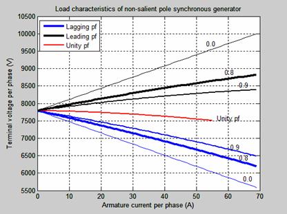
Figure 10. Terminal voltage per phase-armature current characteristic
The terminal voltage per phase-armature current (load current) sometime known as the load characteristic of an alternator (non-salient pole synchronous generator) is shown in Figure 10. The load characteristic of a non-salient pole synchronous generator is based on the condition that the no-induced emf per phase equals the terminal voltage per phase. The voltage regulation depends on the armature current and on the power factor of the load. There is always voltage drop in the terminal voltage for lagging and unity power factor conditions and therefore the voltage regulation values are always positive. In leading capacitive load, the terminal voltage increases as the armature current increases and the regulation in such cases is negative.
Figure 11 shows the excitation of non-salient pole synchronous generator with constant terminal voltage.
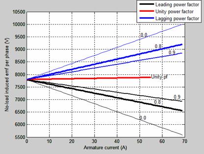
Figure 11. No-load induced emf-armature current characteristics for a constant output voltage
As the lagging power factor increases, the open circuit voltage increases upward to zero lagging power factor while that of the leading power factor decreases downward to zero leading power factor.
The no-load induced emf (open circuit voltage) or internal generated voltage is kept constant. Figure 12(a) is the armature phase current versus terminal voltage per phase. The armature phase current varies directly proportional to the terminal phase voltage for leading power factor load.
The armature phase current decreases as the terminal voltage per phase increases for lagging power factor load in 12(b). In Figure 12(c), the torque angle at point K is zero and the armature current per phase is 58.6A. The terminal voltage at point is 8075.8V which is equal to no-load induced emf. The torque/power or coupling angle is the angle between the no load induced emf and the terminal voltage. This angle also corresponds to the angle between the field flux (rotor) and the armature generated rotating flux. Figure 13 shows the Torque angle-terminal voltage per phase characteristic.
The torque angle varies directly to the terminal voltage per phase for leading power factor load in Figure 13(a) while in Figure 13(b) and 13(c), the torque angle varies inversely to the terminal voltage per phase for both lagging and unity power factor load.
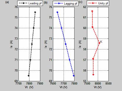
Figure 12. Armature current-terminal voltage characteristics
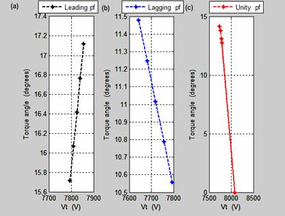
Figure 13. Torque angle-terminal voltage characteristics
The Torque angle-armature current characteristics are shown in Figure 14. The torque angle at leading and lagging power factor load in Figure 14(a) and 14(b) increase as the armature current per phase increases. Figure 14(c) shows the torque angle-armature current characteristics at unity power factor load.
Figure 15 shows the power versus torque angle characteristics of non-salient pole synchronous generator. Figure 15(a) is expressed in percentage while Figure 15(b) shows the real characteristics with the output values.
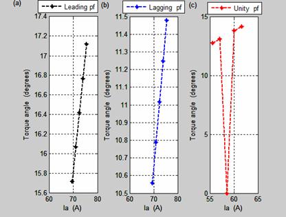
Figure 14. Torque angle-armature current characteristics
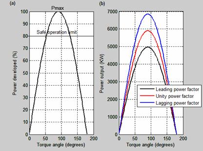
Figure 15. Power-torque angle characteristics of cylindrical rotor synchronous generator
The power out of synchronous generator depends on the power angle or torque. As the torque angle increases, the output power increases and if it decreases, the output power decreases. The maximum output power occurs when the torque angle is 900. Synchronous generator will lose its synchronism if δ which is the torque angle becomes greater than 900 and consequently results in high current generation and mechanical forces. The maximum torque is known as the pull-out torque. Synchronous generator can be loaded to Pmax or Tmax which is the static stability limits.
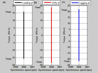
Figure 16. Torque-speed characteristics of non-salient pole synchronous generator
The torque-speed characteristics are shown in Figure 16. The torque-speed characteristics for leading, unity and lagging power factor are shown respectively in Figure 16(a), 16(b) and 16(c). The results show that at unity power factor, the torque is higher than any of the two other power factors. The synchronous speed which is 3000 rev/min remains constant irrespective of the load connected with the synchronous generator.
The effect of the variation of phase angles with the torque angles for leading and lagging power factor loads are shown in Figure 17.
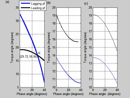
Figure 17. Torque angle-phase angle characteristics
Figure 17(a) shows the intersection of phase angle and the torque angle at K. At point K the new generator will be operating as if it is connected to either lagging or leading factor load.
The value of the torque angle at point K is 16.96 degree while the phase angle at that point is 29.72 degree. The power factor of the new generator at point K is 0.8685 which is greater than that of the original generator. For both lagging and leading power factor as shown in Figure 17(b), the torque angles are inversely proportional to the phase angles. In Figure 16(c), the torque angles fall gradually from its maximum value. As the torque angle reduces, the phase angle increases until it gets to its limit value. The magnitude of the torque angle in leading power factor is more than that of the lagging power factor as it is shown in Figure 17(b) and Figure 17(c) except that of Figure 17(a), where the torque angle of the lagging power factor is greater than that of leading power factor. The original generator ratings and characteristics may be different from that at point K of new rating.
This means that a new generator characteristic can be formed from any original designed non-salient pole synchronous generator whose output parameters may be different from the original, though this is limited to our research.
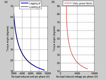
Figure 18. Torque angle versus no-load induced emf per phase characteristics
Figure 18 is the torque versus No-load induced emf per phase characteristics. Torque angle decreases gradually with any increase in open circuit voltage per phase.
Conclusions
The phasor diagrams of non-salient synchronous generator through simulation by MATLAB programs produce results of generator performance analysis. A new generator known as neutral generator is obtained having the same effect on either lagging and leading power factor load. The phase angle and torque are the same for both lagging and leading power factor. The new generator rating and its performance characteristics will be investigated in our further research.
References
1. Abdelela Kh. M., Design of antiwindup AVR for synchronous generator, College of Eng., University of Mousl, 2009, 17(3).
2. Okoro I. O., Agu M. U., Chinkuni E., Basic principles and functions of electrical machines, The Pacific Journal of Science and Technology, 2006, 7, p. 45-51.
3. Ouassaid M., Nejemi A., and Cherkaoui M., A new non-linear excitation controller for synchronous power generator, Conf. on electric power systems, high voltages, electric machines, Tenerife, Spain, 2005, p. 98-103.
4. Rizwan K. M., Atif I., Mouin Ahmed S. K., MouinudIn S., Saifullah P., Multi-phase alternative current machine winding sign, International Journal of Engineering, Science and Technology, 2010, 2(10), p. 79-86.
5. Sen P. C., Principles of electrical machines and power electronics, Second edition, Queen’s University, Kingston, Onatario, Canada, 1996, pp. 296-303.
6. Wadhwa C.L., Basic Electrical Engineering, 4th edition, University of Delhi, New Age International limited, India, 2007, p. 276-302.
7. Prechanon K., Investigation of the critical caring time of power system with synchronous machine model including salency, American Journal of Applied Sciences, 2012, 9(2), p. 1-4.
8. Agarwal R. K., Principles of electrical machine design, S. K. Kataria and Sons, Delhi, India, 2010, p. 399-437.
9. Theraja B. L., A textbook of electrical technology, New Delhi-110 055 India, S. Chand & Company Ltd, 2008.
10. Heudt G., Kalsi S., Kyriakides E., A Short course on synchronous machines and synchronous condensers, 2003, Arizona State University, American Superconductor, America, p. 1-40.