An electronically controlled automatic security access gate
Jonathan A. ENOKELA1*, Michael N. TYOWUAH2
1Department of Electrical and Electronics Engineering, Federal University of Agriculture, P.M.B. 2373, Makurdi, Benue State, Nigeria
2Department of Technical Education, College of Education, Katsina-Ala, Benue State, Nigeria
E-mails: 1 jonajapeno@gmail.com; 2 mikengumom@gmail.com
*Corresponding author, Phone: +234 70 3186 7444
Abstract
The security challenges being encountered in many places require electronic means of controlling access to communities, recreational centres, offices, and homes. The electronically controlled automated security access gate being proposed in this work helps to prevent an unwanted access to controlled environments. This is achieved mainly through the use of a Radio Frequency (RF) transmitter-receiver pair. In the design a microcontroller is programmed to decode a given sequence of keys that is entered on a keypad and commands a transmitter module to send out this code as signal at a given radio frequency. Upon reception of this RF signal by the receiver module, another microcontroller activates a driver circuitry to operate the gate automatically. The codes for the microcontrollers were written in C language and were debugged and compiled using the KEIL Micro vision 4 integrated development environment. The resultant Hex files were programmed into the memories of the microcontrollers with the aid of a universal programmer. Software simulation was carried out using the Proteus Virtual System Modeling (VSM) version 7.7. A scaled-down prototype of the system was built and tested. The electronically controlled automated security access gate can be useful in providing security for homes, organizations, and automobile terminals. The four-character password required to operate the gate gives the system an increased level of security. Due to its standalone nature of operation the system is cheaper to maintain in comparison with a manually operated type.
Keywords
Electronic security, Gate control, Electronic access
Introduction
The security situation in many parts of the world today leaves much to be desired. In Nigeria particularly, the prevalence of armed robbers and other groups that constitute nuisance to the society has led to the loss of lives and properties worth millions of dollars. Many of the attacks that led to the loss have occurred in the homes or in guarded compounds and the attacks took place in spite of the existence of seemingly impregnable security gates that were designed to ward off intruders [1]. The needs for electronically controlled gates that have superior security features to those operated manually thus exist and have been on the increase in recent times [2].
Many attempts have been made to design such gates with various types of security features. In the work by Shoewu and Baruwa [3] a microprocessor was used to monitor two gates which sense the approach of a vehicle. The gates automatically open, wait for a specified time and then close. It is clear that the features of these gates do not provide adequate security since any vehicle can gain entry into the compound. A system that provides efficient gate access and an estate control to perform the job of the gate security guard is discussed in the work by Lau and Choo [4]. The main pitfall of this system is that it uses a telephone to identify visitors; the telephone can be used by anyone who approaches the gate. The development of a computer-controlled security gate system explained by Arulogun et al. [5] allows privileged users to gain entry through a keyless door by using smart card authentication. It is true that smart cards can be stolen thus compromising the security of this system. An attacker only needs to acquire a valid smart card in order to gain entry through the door [6]. A low-cost private office access control system developed and discussed by Khan [7] permits a user with the correct password entered on a keypad to gain entry by controlling an electromagnetic door lock. The fact that passwords belonging to one individual can be learned by another without the owners permission is a major drawback of the system: the rogue can use the stolen password to gain entry into the system. Radio frequency identification (RFID) has been used in conjunction with microcontrollers to control gates to enable vehicles to pass through [8, 9]. Olatinwo and Shoewu [10] have described a system in which swing gates are controlled electronically using microcontrollers and infrared transmitters. This system is only required to close and open gates and has a very limited security feature. In the work done by Adewuyi et al. [11, 12] surveillance cameras are used to capture and recapture the face of the driver as well as vehicle plate numbers. These data are stored in a databank for future comparison with visitors who will only be able to gain entry into a compound through gates if the data match. The system has the disadvantage that users must have been properly documented to enable them pass through the gate.
The system that has been designed in this work uses microcontrollers and radio-frequency transmitter/receiver pair as major components. A microcontroller is programmed to decode a given sequence of keys that is entered on a keypad; the microcontroller commands a transmitter module to send out this code as signal at a given radio frequency. Upon reception of this RF signal by the receiver module, another microcontroller activates a driver circuitry to operate the gate automatically. Some advantages of the system over those described in [5], [6] and [7] include:
(i) It does not need close contact to control the gate; the control can be done from inside the car at a distance.
(ii) It operates as a stand-alone system and does not require a network provider for reception of signals.
(iii) The use of a keypad to generate the code necessary for the opening and closing of the gate enhances the security of the system since it requires very many trials by an intruder to succeed in breaking into the system.
(iv)The features of the system that are controlled by the firmware resident in the memory of the microcontrollers can be easily improved for future upgrade.
The present study aims at designing an electronic automated gate system that can be remotely controlled from a distance. The electronic code of the system has an in-built password that is four characters in length. This code is entered from a handheld unit. The security of the system is enhanced since the code is not easy to break and is only known to the operator.
Materials and method
Architecture of the system
The security access gate system being described in this work is made up of two principal units. The transmitting unit, depicted in the block diagram in Figure 1 consists of a matrix keypad, a microcontroller, and an RF transmitter module. The transmitting unit is portable and can be kept in a car or in a form of transport agreeable to the operator. A certain sequence of characters is punched on the matrix keypad and this is accepted by the microcontroller which sends the code to the RF transmitter module for transmission through the built-in antenna.

Figure 1. Block diagram of transmitting unit
The RF signal is received by the RF receiver module that forms part of the receiving unit whose block diagram is depicted in Figure 2. The RF receiver module decodes the signal received and sends the code to the microcontroller which drives the motor through the driver unit. The receiving unit is an integral part of the gate assembly. The RF transmitter module and receiver module operate at a frequency of 434 MHz.
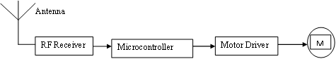
Figure 2. Block diagram of receiving unit
Hardware design
The transmitting unit
The schematic diagram of the transmitting unit is shown in Figure 3. This has a 3×4 matrix keypad containing 12 characters namely 1, 2, 3, 4, 5, 6, 7, 8, 9, #, 0, *. The matrix keypad is interfaced with the microcontroller that is programmed to transmit signal only when it receives code of 4 characters in a given sequence. The sequence 1-3-5-8 has been chosen for the design. The permutation formula given in equation (1) shows that for a 4-character code, it will require 11,880 trials for an intruder to break into the system. A longer character-code will make the system more secure since more trials will be required to break into the system.
|
|
(1) |
In Figure 3, the microcontroller transmits the correct code through its serial port to the RF transmitter module which in turn transmits the modulated signal into the air.
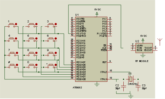
Figure 3. Schematic diagram of transmitting unit
The receiving unit
The schematic diagram of the receiving unit is shown in Figure 4. The signal from the transmitting unit is received and demodulated by the RF Module which passes the code to the microcontroller. The microcontroller verifies the accuracy of the code received and, if it is correct, energizes the dc motor through the driver transistors.
Software design
The transmitting unit has a 3×4 matrix keypad that is interfaced with the microcontroller which is programmed to activate the transmitting unit to transmit RF signal when it receives the code sequence 1358. The flowchart used to develop the program for the transmitting unit is shown in Figure 5.
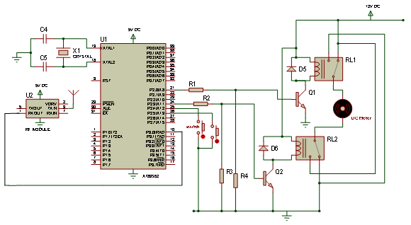
Figure 4. Schematic diagram of receiving unit
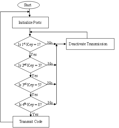
Figure 5. Flowchart for the program of transmitting unit
The RF module in the receiving unit receives transmitted code from its transmitter pair. If the code received is incorrect the gate stays in its present position of open or close. If the code received is correct the system proceeds to check the conditions of the gate and takes decisions as follows:
(i) If the gate is presently closed the system opens it to allow the operator to pass through.
(ii) If the gate is presently opened there is the need to close it after the operator has passed through. This is achieved by entering a wrong code which makes the system to close the gate. The gate will also close if the transmitter goes out of the range of reception of the receiving unit.
The programs for the transmitting and receiving units were written in C language and were built and debugged in the KEIL micro vision 4 integrated development environment [13]. The simulation of the firmware and hardware was carried out using the Proteus Virtual System (VSM) modeling environment version 7 [14]. The resultant hex file was burnt into the program memory of the microcontroller with the aid of a TOP2005 universal programmer [15].
The flowchart used for the program of the receiving unit is shown in figure 6.
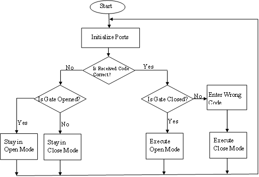
Figure 6. Flowchart for the program of receiving unit
Results and discussion
A typical screenshot taken during program development and debugging is shown in Figure 7.

Figure 7. A typical screenshot during program development
The circuits of the transmitting and receiving units were built on veroboards as shown in Figures 8 and 9 respectively. The receiving unit was connected to a dc motor which formed part of a prototype gate assembly. The gate opened automatically when the correct code (1358) was entered on the keypad of the transmitting unit.
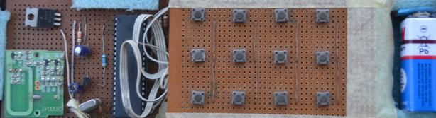
Figure 8. Circuit board of transmitting unit
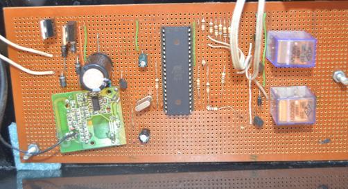
Figure 9. Circuit board of receiving unit
The gate also closed when any wrong key sequence was entered on the keypad or when the transmitting unit moved away from the signal coverage distance, which was measured to be seven (7) meters from the gate. Figures 10 and 11 show the gate in close and open positions respectively.

Figure 10. Prototype gate in close position
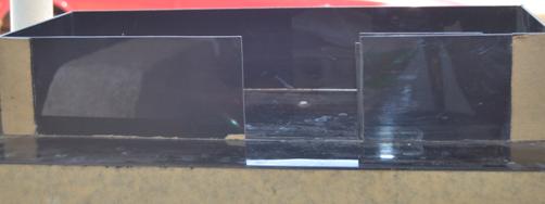
Figure 11. Prototype gate in open position
It was observed that the transmitting unit could communicate flawlessly with the receiving unit up to a distance of seven meters. The signal coverage distance can be increased by using higher power transmission of the RF signal from the transmitting unit. The fact that the gate can be operated from a distance has an important security implication: in the event of a pursuit by criminals the owner of the compound can open the gate while still moving towards it and then close the gate immediately after gaining entry thereby thwarting the intention of the criminals. The system described in this project has been constructed to operate a small gate in order to demonstrate the workability of the design. It can be modified to form part of an electronic toll collection and other entry or pass-through systems that require user identification. The inclusion of password that is to be entered on a keypad makes this design to have an enhanced security. A better security level can be achieved by making the password to have more characters. A bigger gate can still be operated with the control system described but the driver circuitry must use components that can handle more power required to drive the gate.
Conclusion
An electronically controlled automated security access gate has been successfully designed and built in this work. The system is made up of two principal units namely the handheld transmitting unit which communicates with the receiving unit that forms part of the gate assembly. The system achieves a good measure of security by encoding characters and using an RF transmitter-receiver module pair for the transmission and reception of signal over a distance of about 7 meters. The system can be used to keep away intruders from gaining entry into residential buildings, offices and parking lots.
References
1. Ani C. C. (Online), Armed robbery and national security. Nigerian institute of advanced legal studies, Lagos, 2005. Available at: http://nials-nigeria.org/pub/AniComfortChinyere.pdf (accessed 13/10/2013)
2. Chai F. S. (Online), Design of automatic gate mechanism, B. Eng Thesis, University of Malaysia, Pahang, 2009. Available at: http://umpir.ump.edu.my/1138/2/Chai_Fook_Siang.pdf (accessed 8/9/2012)
3. Shoewu O., Baruwa, O. T., Design of a microprocessor based automatic gate, The Pacific Journal of Science and Technology, 2006, 7(1), p. 31-44.
4. Lau K. T., Choo Y. K., A microprocessor-based gate security system, IEEE Transactions on Consumer Electronics, 1989, 35(4), p. 858-862.
5. Arulogun O.T., Olaniyi O.M., Ipadeola A.A., Development of a computer-controlled security gate system, The Pacific Journal of Science and Technology, 2009, 9(2), p. 371-376.
6. Verdult R. (Online), Security analysis of RFID Tags. Available at: http://www.sos.cs.ru.nl/applications/rfid/2008-verdult-thesis.pdf (accessed 10/06/2012)
7. Khan S. R., Development of low cost private office access control system, International Journal of Embedded Systems and Applications, 2012, 2(2), p. 1-7.
8. Bhosale S., Wavhal D.N., Automated tollplaza system using RFID, International Journal of Science, Engineering and Technology Research, 2013, 2(1), p. 455-460.
9. Gunda L., Masuka L., Gonye R., Mhlanga S., Nyanga L., RFID based automatic tollgate system, CIE42 Proceedings, Cape Town, South Africa, 2012, p. 101.1-101.10.
10. Olatinwo S.O., Shoewu O., Development of an automated parking lot management system, African Journal of Computing and ICT, 2013, 6(1), p. 95-108.
11. Adewuyi P.A., Okelola M.O., Jemilehin A.O., An intelligent gate controller using a personal computer and pattern recognition protocols, International Journal of Computational Intelligence and Information Security, 2013, 4(2), p. 13-20.
12. Adewuyi P.A., Okelola M.O., Jemilehin A.O., PIC based model of an intelligent gate controller, International Journal of Engineering and Advanced Technology, 2013, 2(3), p. 601-605.
13. Keil Company. (Online), µvision IDE/Debugger/Simulator. Available at: www.keil.com/product/brochures/uv3 .pdf (Accessed 15/08/2013)
14. Labcenter Electronics. (Online), Proteus design suite. Available at: www.labcenter.com/index.cfm (accessed 20/11/2013)
15. Universal Programmer. (Online), Universal programmer model: TOP 2005. Available at: http://www.nskelectronics.com/files/top_2005_spec.pdf (accessed 15/10/2013)