The iris biometric feature segmentation using finite element method
David Ibitayo LANLEGE 1,*, Kayode Rufu ADEBOYE 2,*, Yusuph Amuda YAHAYA 1, and Audu ISAH 1
1Department of Mathematics/Statistics, Federal University of Technology, Minna-Nigeria, Nigeria
2Department of Mathematics and Computer Science, Ibrahim Badamasi Babangida University, Lapai. Nigeria
E-mail: davidlanlege@gmail.com
* Corresponding author, phone: +2348030528667
Abstract
This manuscript presents a method for segmentation of iris images based on a deformable contour (active contour) paradigm. The deformable contour is a novel approach in image segmentation. A type of active contour is the Snake. Snake is a parametric curve defined within the domain of the image. Snake properties are specified through a function called energy functional. This means they consist of packets of energy which expressed as partial Differential Equations. The partial Differential Equation is the controlling engine of the active contour since this project, the Finite Element Method (Standard Galerkin Method) implementation for deformable model is presented.
Keywords
Multiscale Active Contour Model; Iris Segmentation; Finite Element Method (Standard Galerkin Method); Partial Differential Equation
Introduction
Consistent and protected identification of a person is a key subject in security. In Government and conventional environments, security is usually provided through badges, provision of information for visitors and issuing of keys. These are the most common means of identification since they are the easiest to remember and authenticate. However, these solutions are the most unreliable and they put all components of security at risk. Identity cards can be stolen and passwords can be forgotten or cracked. In addition, security breaches resulting in access to restricted areas of airports or other sensitive areas are a source of concern because of terrorist activities. Although there are laws against false identification, incidents of invasions and unauthorized modifications to information occur daily with catastrophic effects. For example, credit card fraud is rapidly increasing and traditional technologies are not sufficient to reduce the impact of counterfeiting and/or security breaches. Therefore a more secure technology is needed to cope with the drawbacks and pitfalls [1].
Biometrics, the use of biology, with statistical data, provides a powerful answer to this need, since the uniqueness of an individual arises from his/her personal or behavioral characteristics with no passwords or numbers to remember. These include fingerprint, retinal and iris scanning, hand geometry, voice patterns, facial recognition and other techniques. Typically a biometric recognition system records data from a user and performs a comparison each time the user attempts to claim his/her identity.
Biometric systems according to [1] can be classified into two operating modes: verification and identification modes.
In the “verification” mode, the user claims an identity and the system compares the extracted features with the stored template of the asserted identity to determine if the claim is true or false. In the “identification” mode, no identity is claimed and the extracted feature set is compared with the templates of all the users in the database in order to recognize the individual. For such approaches to be widely applicable, they must be highly reliable [1]. Reliability relates to the ability of the approach to support a signature that is unique to an individual and that can be captured in an invariant manner over time. The use of biometric traits requires that a particular biometric factor be unique for each individual so that it can be readily measured, and that it is invariant over time.
Biometrics such as signatures, photographs, fingerprints, voiceprints and retinal blood vessel patterns, all have significant drawbacks. Although signatures and photographs are cheap and easy to obtain and store, they are insufficient to identify automatically with assurance, and can be easily forged. Electronically recorded voiceprints are susceptible to changes in a person’s voice, and they can be counterfeited. Fingerprints or handprints require physical contact, and they also can be counterfeited or marred by artifacts [1].
It is currently accepted within the biometric community that biometrics has the potential for high reliability because it is based on the measurement of an intrinsic physical property of an individual. Fingerprints, for example, provide signatures which appear to be unique to an individual and reasonably invariant with age, whereas faces, while fairly unique in appearance can vary significantly with time and place. Invasiveness, the ability to capture the signature while placing a few constraints on the subject of evaluation, is another problem. In this regard, acquisition of a fingerprint signature is invasive as it requires that the subject makes physical contact with a sensor, whereas images of a subject’s face or iris that are sufficient for recognition can require a comfortable distance. Consideration of reliability and invasiveness suggest that the human iris is a particularly interesting structure on which to base a biometric approach for personnel verification and identification [2].
From the point of view of reliability, the special patterns that are visually apparent in the human iris are highly distinctive and the appearance of a subject’s iris suffers little from day to day variations. In addition, the method is non-invasive since the iris is an overt body that can be imaged at a comfortable distance from a subject with the use of extant machine vision technology. Owing to these features of reliability and non-invasiveness, iris recognition is a promising approach to biometric-based verification and identification of People [3]. Human iris is believed to provide the most secured biometric for personal identification because it has about six times discriminatory features more than order biometric trait. For people to have more confidence, a more secured electronic business transaction mode must be put in place. Hence, a portable low-cost system that uses iris to authenticate business transaction particularly in banking was developed. That is user’s ATM card is made to contain his/her iris templates in addition to the traditional pin. The developed system has the same level of data content protection as the existing ATM cards. The iris camera is usable up to 35 cm to the user. An authentication system on iris recognition is reputed to the most accurate among all biometric methods because of its acceptance, reliability and accuracy. Ophthalmologists originally proposed that the iris of the eye might be used as a kind of optical fingerprint for personal identification [4]. Their proposal was based on clinical results that every iris is unique and it remains unchanged in clinical photographs. The human iris begins to form during the third month of gestation and is complete by the eight month, though pigmentation continues into the first year after birth. It has been discovered that every iris is unique since two people (even two identical twins) have uncorrelated iris patterns [5], and yet stable throughout the human life. It is suggested in recent years that human irises might be as distinct as fingerprint for different individuals, leading to the idea that iris patterns may contain unique identification features. In 1936, Frank Burch, an ophthalmologist, proposed the idea of using iris patterns for personal identification [6]. However, this was only documented by James Doggarts in 1949. The idea of iris identification for automated recognition was finally patented by Aran Safir and Leonard Flom in 1987 [6]. Although they had patented the idea, the two ophthalmologists were unsure as to practical implementation of the system. They commissioned John Daugman to develop the fundamental algorithms in 1989. These algorithms were patented by Daugman in 1994 and now form the basis for all current commercial iris recognition systems. The Daugman algorithms are owned by Iridian Technologies and they are licensed to several other companies [6].
The musculoskeletal system exhibits a complex geometry, difficult to model realistically (multiple organs in contact), a complicated mechanical behaviour (viscoelastic, anisotropic, hyperelastic and non-linear); and complex interactions (e.g. confined cartilages within articulation). While simplified representation such as stick- figures and action lines [7,8] have proven to be useful for many application in biomechanics. They have limited accuracy [9,10] and they are unable to represent large attachment areas and accurately simulate global constraints such as volume presentation and non-penetration.
Improvement in terms of accuracy could be achieved using surface models [7] or equivalent reduced representations such as medial axis [9]. Current interactive modelling methods [8, 11-13] remain time-consuming and are not suitable for clinical use. Indeed, orthopaedists, biomechanicians and kinesiomologists would like to simulate, visualize and navigate through articulation with a minimum amount of manual tasks. Diagnosis tools used in the daily medical practice, especially medical scanner, are becoming increasingly precise, available, standardize, as well as less invasive.
The general aim of this project was to carry out the segmentation of the iris for pattern recognition using the Multiscale Approach. The objectives included:
· Extract the iris from the image;
· Find the pupil/iris and iris/scalera boundaries
· Investigate the reliability and efficiency of the method using mat lab;
· Remap the image with a pair of sine-like and cosine-like Gabor
Material and Method
Active Contours (Snakes) and Equation Formulation
Active contour or deformable models are energy-minimizing curves that deform to fit image features. Snakes are a special case of deformable models as presented [10] snake is an energy-minimizing parametric contour that deforms over a series of time step. Each element along the contour u depends on two parameters, where the space parameter is taken to vary between 0 and N−1, and t is time (iteration): Introduced by [11] snakes are method of attempting to provide some of the post-processing that our own visual system performs. A snake is a continuous curve (possible closed) that attempts to dynamically position itself from a given starting position in such a way that it ‘clings’ to edges in the image. It has built into it various properties that are associated with both edges and the human visual system (E.g. continuity, smoothness and to some extent the capability to fill in section of an edge that have been occluded).
Snake Properties
From now on snake will be referred to as the parametric curve
u(s) = u(x(s),y(s))
where s is assumed to vary between 0 and 1.
(a) The snake must be ‘driven’ by the image. That is, it must be able to detect an edge in the image and align itself with the edge. One way of achieving this is to try to position the snake such that the average ‘edge’ (however that may be measured) along the length of the snake is maximized. If the measure or edge strength is F (x, y) > 0 at the image point (x, y) then this amount to saying that the snake u(s) is to be chosen in such a way that the functional:
|
|
(1) |
is maximized. This will ensure that the snake will tend to mound itself to edge in the image if it finds them, but does guarantee that, in the first place. Given an image the functional may have many local minima (a static problem); finding them is where the ‘dynamics’ arises. An edge detector applied to an image will tend to produce an edge map consisting of mainly thin edge.
(b) If an elastic band were held around a convex object and then let go, the band would contract until the object prevent it from doing so further. At this point the band would be moulded to the object, thus describing the boundary. Two forces are at work here, first that providing the natural tendency of the band to contract, and secondly the opposition force provided by the object. The band contracts because it tries to minimize its elastic energy due to stretching. If the band were describe by the parametric curve u(s) = u(x(s),y(s)) then the elastic energy at any point I is proportional to:
|
|
(2) |
That is, the energy is proportional to the square of how much the curve is being stretched at that point. The elastic band will take up a configuration so that the elastic energy along its entire length, given the constraint of the object, is minimized. Hence the band assumes the shape of the curve u(s) = u(x(s),y(s)) where u(s) minimizes the functional subject to the constraints of the object.
|
|
(3) |

(c) One of the properties of edges that are difficult to model is their when they can no longer be seen. If we were looking at a car and a person stood in front of it, few of us would have any difficulty imagining the contours of the edge of the car that were occluded. There would be ‘smooth’ extension of the contours on either side of the person. If the above elastic band approach were adopted it will be found that the formed straight line were the car was occluded (because it tries to minimize energy, and thus length in this situation). If however the band had some stiffness (that is a resistance to bending as for example displayed by s flexible bar) then it would tend to form a smooth curve in the occluded region of the image and be tangential to the boundaries on either side.
Again a flexible bar tends to form a shape so that its elastic energy is minimized. The elastic energy in bending is dependent on the curvature of the bar that is second derivatives. To help force the snake to emulate this type of behavior, the parametric curve u(s) = u(x(s),y(s)) is chosen so that it tends to minimized the functional
|
|
(4) |

which represent a pseudo-bending energy term of course, if a snake were made too stiff then it would be difficult to force it to conform to highly curved boundaries under the action of the forcing term in (1).
Three desirable properties of snakes have now been identified. To incorporate all three into the snake at once the parametric curve u(s) = u(x(s),y(s)) representing the snake is chosen so that it minimizes the:
|
|
(5a) |

Equation (5a) can better written as
|
|
(5b) |

Here the terms α(s)≥0 and β(s)≥0 represent respectively the amount of stiffness and elasticity that the snake is to have. It is clear that if the snake approach is to be successful then the correct balance of these parameters is crucial.
|
a) |
b) |
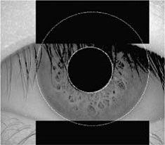
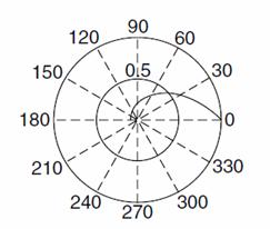
Figure 1. a) Iris localization without noise; b) Polar (θ,r) Unwrapping the Iris
Equation Formulation
Clearly the ideal situation is to seek a local minimum in the locality of the initial position of the snake. In practice the problem that is solved is
|
|
(6) |
where H2[0.2π] denotes the class of real valued functions defined on [0.2π] that have ‘finite energy’ in the second derivatives (that is the integral or the square of the second derivatives exists) and H02[0.2π] is the class of functions in H02[0.2π] that are zero at s=0 and s=2π.
To see how this relates to finding a minimum consider u(s) to be a local minimum and u(s)+εv(s) to be a perturbation about the minimum that satisfies the same boundary conditions (i.e. v(0)=v(2π)=0) clearly.
Considered as a function of ε, I(ε)=εI(u(s))+εv(s) is a minimum at ε=0.
Hence the derivation of I(ε) must be zero at ε=0. Equation (6) is therefore a necessary condition for a local minimum.
Standard arguments in the calculus of variations show that problem (6) is equivalent to another problem, which is simpler to solve:
· Find a curve u(x(s),y(s))εθ4[0.2π]×θ4 [0.2π] that satisfy the pair of fourth order ordinary differential equations:
|
|
(7) |
|
|
(8) |


In practice, α(s) and
β(s) are usually taken to be constant, arbitrarily chosen to be ![]() hence equations
hence equations ![]() and
and ![]() become:
become:
|
|
(9) |
|
|
(10) |
Together with the boundary conditions:
|
|
(11) |
The vectors x and
y contain the ![]() and y coordinates respectively
of each element in the model; they represent the position of the snake
elements, both before and after adjustment to conform with the internal forces.
and y coordinates respectively
of each element in the model; they represent the position of the snake
elements, both before and after adjustment to conform with the internal forces.
Multiscale Method for Active Contours
There are so many
Multiscale approaches ranging from polar coordinate θ0,
θ1, θ2, θn-1 etc. But this
work employs the use of ![]() (Multiscale
for polar coordinate) for its analysis.
(Multiscale
for polar coordinate) for its analysis.
|
|
|
By using the appropriate value for θ1, θ2, θ3… θn
|
|
|
This is the standard Galerkin Method.
From![]() above we consider an approximate
solution of the form:
above we consider an approximate
solution of the form:
|
|
(12) |
where U0(x) satisfies the
non-homogeneous boundary condition at the boundary and Ui(x),
i=1,2,3,…n are basis functions which satisfies the homogeneous boundary
conditions in equation ![]() and the Ui(x),
i=1,2,3,…n are such that:
and the Ui(x),
i=1,2,3,…n are such that:
i. Ui(x), i=1,2,3,…n are linearly independent
ii. Ui(x) satisfies the homogeneous
iii. Ui(x) is of the form (x-a)i(b-x) or (b-a)(b-x)i, i = 1,2,3,…, n but if it is in the interval [0.2π] then we have xi(2π-x) or (2π-xi) where is frequently used.
We substitute the
appropriate solution U(x) into the b.v.p to equation ![]() obtains a residual in the form:
obtains a residual in the form:
|
|
|
But our U0(x) can be obtained from [0.2π] as follows:
|
|
|
We find the values of θi
and then substitute into equation![]() and
evaluate
and
evaluate
|
|
|
|
|
(12) |
|
|
(13) |
|
|
(14) |
|
|
(15) |
|
|
(16) |
|
|
|
|
|
(17) |
|
|
|
Collecting like terms gives:
|
|
(18) |
|
|
(19) |
Results and Discussion
Making (19) orthogonal by firstly multiplying each term by (x-x2) and integrating over [0.2 π] gives:
|
|
(20) |
|
|
(21) |
|
|
(22) |
|
|
(23) |
|
|
(24) |


Multiplying ![]() by -1260, we have:
by -1260, we have:
|
|
(25) |
Similarly, making (19) orthogonal by multiplying each term of by (x2-x3), integrating over [0.2π] and multiplying result by -2520 we have:
|
|
(26) |
Again making (19) orthogonal by thirdly multiplying each term of (18) by (x3-x4), integrating over [0.2π] and multiplying result by -12600 we have,
|
|
(27) |
We do same for (x4-x5) and multiply result by -2520 to get
|
|
(28) |
Putting these equations in augmented matrix form we obtain below:
|
|
|

We now solve for θ1, θ2, θ3, θ4, using Gaussian Elimination method. We have the emerging final matrix as below
|
|
|
|
|
(29) |


From the solution by Finite Element Method Standard Galerkin Method (Figures 2-4) we can see that the smaller the value of the segmentation parameter h, the better the image segmentation. Hence the smaller value of h causes the segmentation steps/phases in this case x0, x1, x2,… to be closer to each other, thus eliminating possible errors which would otherwise occur in taking lumps of the image pixels or voxels at a time. Thus it is preferable to use a smaller value of h for a more efficient segmentation to take place.
Although the large value of h, faster the convergence speed, it may not be adequate to give a good curve of the snake. On the other hand, the smaller the value of h, the slower it takes to converge, but it gives a good curve around the region of interest.
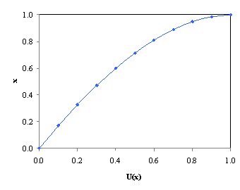
Figure 2. Graph for Segmentation with parameter h=0.1 and at interval [0.2π]
This framework attempts to immunize an energy associated with the current contour as a sum of an internal and external energy.
The research involves the use of snake method. Snake is an energy minimizing, deformable spine influenced by constraint and image forces which pull it towards object contours. Snakes are greatly used in applications like object tracking, shape recognition, segmentation, edge detection, stereo matching. Snakes may be understood as a special case of general technique of matching a deformable model to an image by means of energy minimization. Snake is an “active” model as it always minimizes its energy functional and therefore exhibits dynamic behavior.
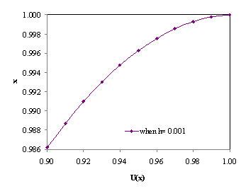
Figure 3. Graph of Segmentation with parameter h=0.001 and at interval [0.9,1.0]
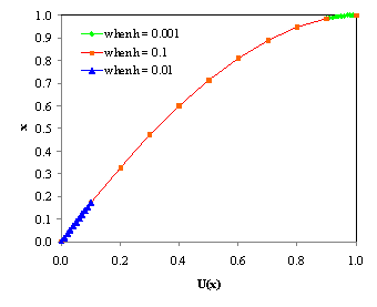
Figure 4. Graph for segmentation with parameter h=0.1, 0.01 and 0.001
This method introduces a multiscale approach for edge detection by using active contour model for efficiently detecting the iris region for use in the future extraction stage. Once this is done, a combined feature extraction scheme using Matlab algorithm components to extract all texture information from orientation in horizontal and vertical details was employed to obtain useful results.
In the application of image processing tools, an image is first passed through the Proportional Integral Derivative (PID) Controller filter which the low passed image then has its intensity adjusted by the image intensity adjustment tools. Then, finally Sobel edge Detector is used to enhance the outline of the image. This order is necessary for the processing because Sobel edge detector is very sensitive to noise. As such, the noise needs to be filtered out before the edge detector application. More so, since the gradient of the Sobel edge detector is related to the change in intensity at the edge of an object, the image intensity adjustment is used to produce a higher contrast image. As image intensity adjustment can improve the intensity of the image as well as noise within the image, the noise must be filtered out before the intensity adjustment. Gaussian low pass is employed to reduce the noise effect.
Further research in the segmentation of medical images will strive towards improving the accuracy, precision, and computational speed of segmentation methods, as well as reducing the amount of manual interaction. Accuracy and precision can be improved by incorporating prior information from atlases and by combining discrete and continuous – base segmentation methods. For increasing computational efficiency, multiscale processing and parallelizable methods such as neural networks appear to be promising approaches. Computational efficiency will be particularly important in – real time processing applications. Possibly the most important question surrounding the use of image segmentation is its application in clinical settings. Computerized segmentation methods have already demonstrated their utility in research applications and are now garnering increased use for computer aided diagnosis and radiotherapy planning. It is unlikely that automated segmentation methods will ever replace physicians but they will likely become crucial elements of medical image analysis. Segmentation methods will be particularly valuable in areas such as computer integrated surgery, where visualization of the anatomy is a critical component. Active contour are a method for segmentation based on minimizing the energy of a continuous spline contour subject to constraints on both its autonomous shape and external forces derived from a superposed image that pull the active contour toward Image features such as line and edges. The contour is initially place near an edge under consideration, and then image forces and the user-defined external constraints draw the contour to the edge in the image.
References
1. Wayman J., Jain A., Maltoni D., Biometric Systems, Technology, Design and Performances Evaluation, 2005, Springer-Verlag London UK.
2. Wildes R., Iris Recognition an Emerging Biometric Technology, Proceeding of the IEEE, 1997, 85, p. 1348-1363.
3. Daugman J., High confidence visual recognition of persons by a test of Statistical Independence, IEEE Transactions on pattern Analysis and Machine Intelligence, 1993, 15, p. 1148-1161.
4. Muron A., Pospisil J., The Human iris Structure and its usages, Physica, 2000, 39, p. 87-95.
5. Blemker S., Asakawa D., Gold G., Delp S., Image-based Musculoskeletal Modeling: Application, advance, and future Opportunities, Journal of Magnetic Resonance Imaging, 2007, 25(2), p. 441- 451.
6. Blemker S., Delp S., Three- dimensional representation of Complex Muscle architectures and geometries. Annals of Biomedical Engineering, 2005, 33(5), p. 661-673.
7. Bezdek J. C., Hall L. O., Clarke L. P., Review of MR Image Segmentation Techniques Using Pattern Recognition, Med. Phy., 1994, 20, p. 1033-1048.
8. Chan W. P., Lang P., Chieng P. U., Davison P. A, Huang S. C., Genant H. K., Three – dimensional Imaging of the Musculoskeletal System: an Overview. J. Formos Med Assoc, 1991, 90, p. 713-722.
9. Kass M., Witkin A., Terzopoulos D., Snakes: Active Contour Models, Int. Journal Comp. Vision, 1987, 1, p. 321-331.
10. Cohen L. D., Cohen I., Finite Element Method for Active Contour Models and Balloons for2 – D and 3 – D Images, IEEE Transactions on Pattern Analysis and Machine Intelligence, 1993, 2, p. 521-531.
11. Stalbom M., Musculoskeletal System Simulation to Analyze Muscle Force and Movement Pattern, Master Thesis from Royal Institute of Technology Department of Mechanics, 2008 SE - 10044 Stockholm, Sweden.
12. McInerney T., Terzopoulos D., A Dynamic Finite Element Surface Model For Segmentation and Tracking In Multidimensional Medical Image With Application To Cardiac 4D Image Analysis, Comp. Med. Image. Graph., 1995, 1, p. 321-331.
13. Singh L., Von Kurowski, Chiu M. Y., Cardiac MRI Segmentation Using Deformable Models. Proc.IEEE Conf. on Computers and Cardiology, London 12, 1993, pp.160-163.
14. Lanlege D.I., Iris Image Biometric Features Segmentation Using Multiscale Methodology, Ph.D. Thesis preparation, 2014
15. Adeboye K. R., Yahaya Y. A., Lanlege D. I., Effective Way of Noise Smoothing During Image Processing Using Multiscale Proportional Integral Derivative (PID) Filter Controller, Journal of Multidisciplinary Research (IRJSET), 2013, 2(2), p. 17-24.