Application of PQR theory for control of a 3-phase 4-wire 4-legs shunt active power filter in the αβο-axes using 3d-svm technique
Ali CHEBABHI1, Mohammed-Karim FELLAH1, Mohamed-Fouad
BENKHORIS2
1 ICEPS Laboratory (Intelligent
Control & Electrical Power Systems),
2 IREENA Laboratory (Institut de Recherche en Electronique et Electrotechnique de Nantes Atlantique), University of Nantes at Saint Nazaire, France.
E-mail(s): chebabhiali@gmail.com; mkfellah@yahoo.fr; Mohamed-Fouad.Benkhoris@univ-nantes.fr
* Corresponding author, phone: +213560740793
Abstract
This article discusses and compares two control strategies applied to a 3-phase 4-wire 4-leg shunt active power filter. These two control strategies, including the cross-vector theory called CV theory and the direct method called PQR theory, are based on the instantaneous control of active and reactive power. On one hand, it is shown that, in some cases, cross-vector theory requires elimination of the zero sequence currents in a 3-phase 4-wire 4-leg shunt active power filter, which needs a power storage element, and on the other hand pretreatment system voltage is necessary to obtain compensated sinusoidal current and a degree of freedom. By relying on the cross-vector theory, the PQR theory is used to extract and remove harmonic currents components. In this control technique, there are two internal current control loops and an external voltage control loop, these control loops have been realized by PI controllers when applied 3D-SVM of switching technique. We choose as criteria for comparison the transient and the Total Harmonic Distortion in the line current. A series of simulations in MATLAB/ Simulink environment have been presented and discussed to show the performance of the two control strategies.
Keywords
3-phase 4-wire 4-leg SAPF; CV theory; PQR theory; Harmonic currents
Introduction
The development of systems based on power electronics leads to an increasing number of network-connected non-linear loads. This has been applied in both in industry (motor drive, rectifier) and in the domestic sector (computer, TV) [1]. These non-linear loads absorb non-sinusoidal currents, which lead both to the appearance of a disturbing phenomenon which is becoming more and more extensive, causing genes and even malfunctions in electrical equipment, and to the worries of the distributors 'electrical energy [2].
This is nothing other than the harmonic distortion. The result is the presence and spread throughout the network harmonic currents, resulting in most cases odd rows. This is why the improvement of the electrical energy is important and it is interesting to find solutions in order to improve further but cleaner and more durable.
In view of these findings, it therefore seems important to limit the propagation of these harmonic currents to ensure satisfactory quality of energy. It is with this aim that power electronic devices should be used to help clean up the network. This could be achieved by using the inverter as an active power filter by adding references of harmonic line currents to the command which already controls the powers [3].
This solution consists of implementing a filter called active, the principle was proposed in the early eighties [4,5]. This device is a power converter which injects in the electricity grid harmonic currents equal to those absorbed by the load, but in opposite phase with them. Thus, the filter is constantly adapting to the harmonic currents on the network and allows for compensation of all harmonics. These active power filters come in different structures and there is a wide variety of commands depending on whether one wants to correct voltages (series filter) or current (parallel filter) [3]. This is currently the most effective solution.
Several studies have shown that the conventional three-phase active power filter cannot compensate the disturbances due to single-phase non-linear loads connected to a four-wire network. [6]. Thus, the main objectives of this work was to study in detail the technical control of shunt active power filter with four arms to eliminate the harmonic of currents flowing in the network and the zero-sequence current [7], by relying on the cross-vector theory, which was used for extracted and removing harmonic currents. The PQR method was introduced to eliminate the zero-sequence current away. In the PQR theory the independence between the three variables plp, plq and plr offers a degree of freedom equal to 3, this means that it is possible to set each power variable without affecting other variables [8].
Eventually, to ensure a good performance, the conventional PI controllers was used when applied 3D-SVM of switching technique to control the 4-legs inverter. The simulation results of the two studied methods will be presented in order to prove the efficiency of them.
Materials and method
Four arms shunt active power filter
The underlying principle of four arms shunt active power filter is that the current load is sampled and calculated fast. As for that the harmonic current is caught (Figure 1). Through the compensation current generating circuits, the load harmonic current is rejected in the grid connection point of power system and load, so that the supply current is sinusoidal. The Four arms shunt active power filter is an arbitrary current generator in fact, which can generate the load harmonic currents so that the input current of required power is sinusoidal [9].
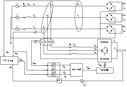
Figure 1. The main circuit of the 3-phase 4-wire 4-legs shunt active power filter
Algorithms of extracted and removing harmonic currents
The cross-vector theory
Cross-vector theory defines instantaneous active and reactive power
respectively by the scalar and vector product of the voltage and the current
space vectors in the time domain in a three-phase four-wire system [6, 10].
Here, the instantaneous active and reactive powers have the same physical
meaning of the instantaneous real and imaginary powers in pq theory. The authors prefer to express it as
instantaneous real and imaginary power to distinguish it from the traditional
definition of active and reactive power in the frequency domain.
|
|
(1) |

Figure 2 present schematic principal of the cross-vector theory [11].
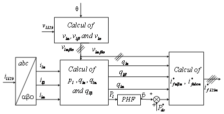
Figure 2. Schematic diagram of the cross-vector theory (Adapted from [11])
The instantaneous power is calculated as follows:
|
|
(2) |

From equation (2), we can deduce the corresponding current components:
|
|
(3) |
|
|
(4) |


with: ![]()
Table (1) summarizes the modes of possible compensations:
Table 1. Modes of compensation of the cross-vector theory
|
Type of compensation |
Parameter of control |
|
Compensation of the harmonic of currents |
|
|
Compensation of
reactive power |
|
|
Compensation of the harmonic of currents and reactive
power |
|
We selected to compensate for at the same time the
harmonics of current and reactive energy, the equation (4) will thus become:
|
|
(5) |

with: ![]()
The inverse Concordia transform calculates the reference currents in the abc-axes as follows:
|
|
(6) |

The PQR theory
The PQR theory is effected by double
transformation process [7]. A first transformation of voltages and line
currents from the abc-axes to αβο-axes, then a second from
the αβο-axes
to the pqr-axes [8,9].
|
|
(7) |
|
|
(8) |


The transformation of simple connection point voltages and line currents of the load allows having the following two equations:
[7,8] Proposes a new reference called α'β'o'-axes turning around the axis o of a![]() angle
to align the instantaneous spatial voltage vector
angle
to align the instantaneous spatial voltage vector ![]() to
the p-axis of pqr-axis of reference as specified in
Figure 4:
to
the p-axis of pqr-axis of reference as specified in
Figure 4:
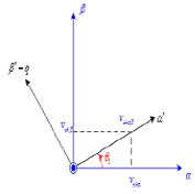
Figure 3. Relation between αβo-axes and α'β'o'-axes
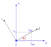
Figure 4. Relation between α'β'o'-axes and pqr-axes
This transformation has for currents:
|
|
(9) |

In the same way, we find the following relations:
|
|
(10) |
Then [7] proposed to make another transformation of the α'β'o-axes 'by a rotation of the axes around the axis β', what was known as the pqr-axes as shown in Figure 3.
Then we get:
|
|
(11) |

In the same way, we find:
|
|
(12) |
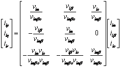
After a simple development, we will have the final relationship between
the currents in the pqr-axes and αβo-axes:
|
|
(13) |
The expression of the instantaneous active and reactive power in the pqr-axes is given by:
|
|
(14) |

Table 2 summarizes the modes of possible compensations:
Table 2. Modes of compensation of the pqr theory
|
Type of compensation |
Parameter of control |
|
Compensation of the harmonic of currents |
|
|
Compensation of the harmonic of currents and reactive
power |
|
By compensating for the harmonics of current and reactive power the
currents of reference of the filter in the PQR reference are calculated from the
equation (14) as follows:
|
|
(15) |

Figure 5 presents schematically the principal of the PQR theory.
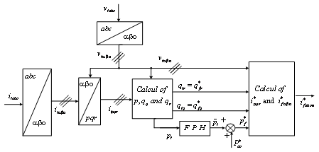
Figure 5. Schematic diagram of the pqr theory
The system parameters considered for simulation and the load specifications are given in table 4.
Table 4. System parameters for simulation and load specifications
|
Capacitance of the capacitor |
5 mF |
|
coupling impedance Rf ,Lf |
0.1 mΩ, 0.1 mH |
|
the source voltage and frequency |
220 V, 50Hz |
|
Source impedance Rs ,Ls |
1 mΩ, 1 mH |
|
Line impedance Rch ,Lch |
1 mΩ, 1 mH |
|
Load impedance Rl ,Ll |
5Ω, 10 mH |
Results and Discussion
Simulation results for the proposed control strategies are shown in Figures 6 to 15.
Simulation results before compensation
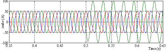
Figure 6. Phase Currents before compensation
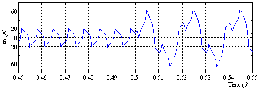
Figure 7. Neutral Current before compensation
Figure 6 shows the current load waveform. This is a very distorted and non-sinusoidal before and after unbalanced.
Figure 7 shows the shape of the neutral current with a maximum value of 20A before unbalanced load and 60A after in the unbalanced load.
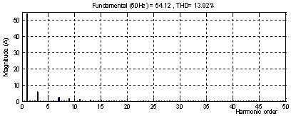
Figure 8. %THD load current before compensation
Simulation results with the CV theory
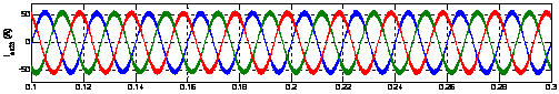
Figure 9. Source currents after compensation with the CV theory
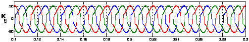
Figure 10. Load current after compensation with the CV theory
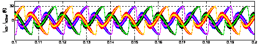
Figure 12. Injected currents by the active power filter with the CV theory
Simulation results with the PQR theory
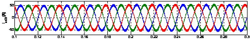
Figure 13. Source currents after compensation with the pqr theory
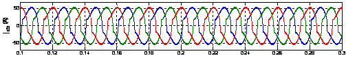
Figure 14. Load current after compensation with the pqr theory
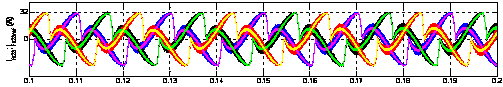
Figure 15. Injected currents by the active power filter with the pqr theory
Figure 9 shows the source current waveform after filtering which is sinusoidal. Figures 10 and 14 represent the shape of the load current, it is a non-sinusoidal current and highly deformed. Figures 11 and 15 show the shape of the neutral current which does not exceed its maximum value 11.5 A. Figures 12 and 16 represents the active power filter injected currents.
Figures 13 shows the first phase source current's THD for the two theories, the total harmonic distortion (THD) is 1.67% for the CV theory Figure 13 and 1.54% for the PQR theory.
Conclusion
From the obtained results it is seen that the compensation performance of APF is almost similar with all two methods, with the advantage of avoiding the time-consuming αβo-axes to PQR-axes.
Also, the controller was capable of eliminating the current flowing in the neutral line. Finally, the simulation results validated both the steady state and dynamic behavior of the proposed controller.
References
1.
Chebabhi A., Fellah M. K., Rouabah
N., Khodja
D. J. Commande d’un filtre actif
shunt par la technique de control directe de puissance basée sur le flux
virtuel. Conférence
International sur l’Electronique de puissance et les Entraînements Electriques
ICEED. 2011,
2. Akagi H., Kanazawa Y., Nabae A., Instantaneous reactive power compensators comprising switching devices without energy storage components, IEEE Transactions on Industry Applications, 1984, IA-20(3), p. 625-630.
3. Soares dos Reis F., Jorge Antonio V. A. S., Kevin T. F. D. A., Reinaldo T. J., Active Shunt Filter for Harmonic Mitigation in Wind Turbines Generators, Pontifical Catholic University of Rio Grande do Sul School of Elcctrical and Computer Engineering Av. Ipiranga 6681, Porto Alegre, RS, CEP 90619-900, Brazil.
4. Gycgyi L., Strycular E. C., Active AC power filters, IEEE lAS Annual meeting, 1976, 19, p. 529-535.
5. Akagi H., Kanazawa Y., Nabae A., Generalized theory of the instantaneous reactive power in three-phase circuits, Proceeding International Power Electronics Conference, Tokyo, Japan, 1983, pp. 1375-1386.
6. Lam C. S., Cui X. X., Choi W.H., Wong M. C., Han Y. D., Minimum DC-Link Voltage Design of Three-Phase Four-Wire Active Power Filters, IEEE, 2012, pp. 978-982.
7. Kim H., Blaabjerg F., Bak J. B., Choi J., Instantaneous power compensation in three- phase systems by using p-q-r theory, IEEE 32nd Annual Power Electronics Specialists Conference , 2001 PESC'01 , 2 , pp. 478-485.
8. Kim H., Akagi H., The instantaneous power theory on the rotating p-q-r reference frames, Proceedings of the IEEE International Conference on Power Electronics and Drive Systems, 1999 PEDS '99. 1999.
9. Kanaan H. Y., Hayek A., Al-Haddad K., Averaged-Model-Based Nonlinear Control of a PWM Three-Phase Four-Leg Shunt Active Power Filter, Proceedings of the IEEE, Electrical and Computer Engineering Canadian Conference, 2007. CCECE, pp. 1002-1005, 22-26 April 2007.
10. Hyosung K., Blaabjerg F., Bak-Jensen B., Choi J., Instantaneous power compensation in three-phase systems by using p-q-r theory, IEEE Transactions on Power Electronics, 2001, 17(5), p. 701-710.
11. Peng F. Z., Ott G. W. Jr., Adams D. J., ‘Harmonic and reactive power compensation based on the generalized instantaneous reactive theory for three-phase four wire systems, IEEE Trans on Power Electronic, 1998, 13(6), p. 1174-1181.