Coupling series two five-phase asynchronous machine powered by a single voltage inverter
Samir ABBAR*, Karim FELLAH, Fouad BENKHORIS
Electrical Engineering Department, ICEPS Laboratory, Djillali Liabes University, Sidi Bel Abbes, 22000, Algeria
E-mails: amirist81@yahoo.fr; mkfellah@yahoo.fr; mohamed-fouad.benkhoris@univ-nantes.fr
Abstract
Multi-phase machines are present in the fields of marine, rail traction, petrochemical industry, aviation, automotive. One of the benefits of these kings of machines is the fact that is possible to combine several series machines and order independently of the other. This article aims to spread an equally important role in the study of multi-stage machines. The study leads to the drive system of machines, their coupling modes, their feeding mode which is quite different and a preview on their principle of control.
Keywords
Multi-phase control; Voltage Inverter; Asynchronous; Independent control
Introduction
Since the design of the first multi-phase induction machine (five-phase) in 1969 [1,2] the interest of multiphase drive systems powered by converters has risen sharply [3-5]. An important property of this machine, is that the new set of equations contains only two components (α, β; stationary α -β axis “Clark transformation”), which leads to coupling between the stator and rotor components as the other three (x, y, o; zero sequence components and the non-sequential components) are not coupled. The situation remains the same after application of the rotational transformation.
This transformation fallows a vector control of the torque and flux with the two Components only of the axis stator current (d, q; synchronous d -q axis “Park transformation”), the other two components; the axis (x, y) is regarded as degrees of additional freedom.
Therefore, it is possible to connect the stator windings of the two machines so that five-phase machine sees axis current component (d, q) and the other axis of the current components (x, y) and vice versa, it would become possible to completely and independently control the speed (position, torque) of the two machines with the power of these machines is made from a single voltage inverter. In simple terms, it is possible to perform vector control of these two machines fed by a single voltage converter provided that the stator windings of both machines are connected in series and an appropriate transposition of the phases is carried out, so that the five “5 “current producing the rotating magnetic force in the first machine, do not produce rotating magnetic force in the second [6-9].
This study leads to the drive system of the machines, their mode of coupling, their feeding mode which is quite different and an overview of their principle of control.
Two-motor drive with two quasi five-phase
For machine n-phases, the spatial displacement between two consecutive phases is equal to 2π/N (where N = phase’s number)
|
|
(1) |

where T= Concordia transfer matrix; N = phase’s number; π= 3.14 rd.
The decoupling transformation matrix for such a five-phase machine is given with (1):
|
|
(2) |

The underlying idea of the concept of stator winding series connection is that flux/torque producing currents of one machine must be non-flux/torque producing currents for all the other machines within the drive system [5;8].
The possibility of achieving this for a configuration consisting of two machines of the structure shown in Figure 1 is investigated next. It is assumed that both machines operate in steady state and that the required phase currents for flux/torque production are given with sinusoidal functions (α= 2π/5).
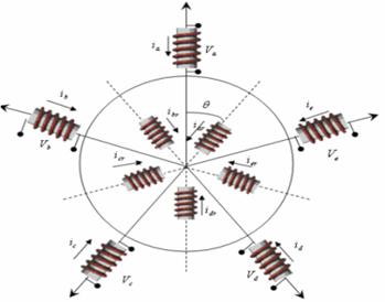
Figure 1. Asymmetrical five-phase machine’s stator winding
To make the study of this model easier, the choice of note (A, B, C, D, and E) indices voltages at the output of the inverter, and (a, b, c, d, and e) the indices of voltages and currents of the two machines (the index '1' means the first machine and the index '2', the second).
|
|
(3) |

where ia, ib, ic, id and
ie : phase current of the first machine; ω1,2: First
and second machine source voltage angular frequency , ![]() .
.
Let the inverter current references are created according to:
|
|
(4) |

where ia2, ib2, ic2, id2and ie2: phase current of the second machine
and let the current control be ideal, so that the inverter output currents may be taken as equal to the inverter current references of equation (4). The inverter phase currents are identically equal to the phase currents flowing through machine 1 [9].
However, for the second machine, due to the phase transposition introduced in equation (4), the following holds true:
ia2= iA*
ib2=iD*
ic2=iB* (5)
id2=iE*
ie2=iC*
where * = reference value for controller
Two-motor drive with a quasi-five-phase machine and a two-phase machine
It is interesting to note that the phase rotation required directly follows the Concordia decoupling said transfer matrix.
· 1st step: The first two phases of the two machines are directly in series, necessary for the implementation phase is zero (which follows the first column of the transfer matrix Concordia).
· 2nd step: the phase "2" (b1) of the first machine is connected to the stage "3" (c2) of the second phase rotation (second column of the transfer matrix Concordia).
· 3rd step: (c1) of the first machine is connected to the "5" phase (e2) of the second, and the phase rotation is (2) (third column of the transfer matrix Concordia).
· 4th step: (d1) of the first machine is connected to the "7" phase of the second but, since the machine is five phase adjustment has taken place and the phase '4' of the first will be logged to the phase "2" (7-5= 2) (b2) of the second, and the phase rotation Concordia transfer matrix. This follows the fourth column.
· 5th step: phase '5' (e1) of the first machine is connected to the "4" phase (d2) of the second, which corresponds to a phase rotation equal to (4).
From this basic consideration, it is possible to construct a connection table as shown in Table 1. The schema matching these connections is in Figure 2.
Table 1. Connectivity matrix for the five-phase case
|
|
A |
B |
C |
D |
E |
|
M1 phase’s |
1 |
2 |
3 |
4 |
5 |
|
M2 phase’s |
1 |
3 |
5 |
2 |
4 |
|
M1 & M2 indexes correspond to the first and second respectively Machine |
|||||
To verify this concept, ideal sinusoidal currents were used. Suppose that the first machine has provided a couple and a given flow rate when powered by sinusoidal currents ideals of effective angular frequency equal to ω1. Similarly, the second machine with the sinusoidal current of angular frequency equal to ω2 [2,10-11].
According to the connection diagram shown in Figure 2, current source simultaneously correspond to the phase currents of the first machine (see Table 2).
Table 2. The two-phase machine stator currents
|
Current components |
M1 |
M2 |
|
|
|
|
|
|
|
|
|
X |
|
|
|
Y |
|
|
|
O |
0 |
0 |
Figure 2. Connectivity of two five-phase machines
Coupling Series Two five-phase Asynchronous Machine Powered by a Single Voltage Inverter
A multi-phase machine advantage is being able to combine several machines and for the series independently of each other [3].
After the coupling of two machines, powered by a suitable inverter (Fig. 2), under these conditions, it is possible to reconstruct the phase voltages of the inverter, this is mentioned in equation (6) [6,11].
|
νE=νes1+νds2 |
(6) |


where νA, νB, νC, νD, νE voltages to the output of the inverter; νas1, νbs1, νcs1, νds1, νes1: stator voltages of the first machine; νas2, νbs2, νcs2, νds2, νes2: stator voltages of the second machine
After applying the transformation to the Concordia transfer matrix (equation (2)), the obtain components (α, β), (x, y) and zero-sequence that are completely decoupled (equation 7).
|
|
(7) |

where: Lcs and Los are respectively the cyclic and the homopolar inductance.
These components (α,β) and (x, y) is completely independent, it possible to apply two different frequencies to each of the two rotations subsets: s1, being the angular frequency of the stator magnitudes of the first machine s2 that of the second [1], such that:
|
|
(8) |
where θ: Electrical angle between the first phase to the first phase stator and the rotor.
|
|
(9) |

Model for simulation
This model shows that of five-phase Machine discussed in precedent paragraph. The difference lies in the value resistors, inductors, and frequency of rotations [8]. Are the stator flux of the first and the second machine respectively (equation given in 10 & 11):
|
|
(10) |
|
|
(11) |


Given the duration of start-up of the two machines, the simulation is done as follows: the two machines are fed at time t = 0, empty to be followed by the application of a load of 2 Nm t = 1.9s on the first and 3 nm at t = 2.8s on the Figure 3.
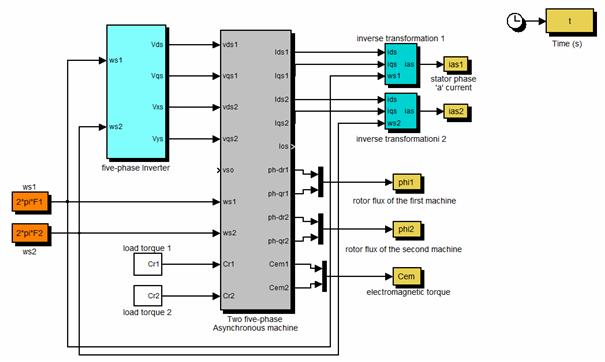
Figure 3. Diagram of coupling simulation series of five-phase two asynchronous machines
Results and discussion
Figure 4 start simulation results of five-phase two asynchronous machines coupled in series and powered by a single voltage inverter. Figure 4, show the results of the simulation of the load starting process asynchronous motors powered by a voltage inverter, followed by applying a load of 2 Nm at time 1.9s on the first and 3Nm the second time in 2.8s.
|
|
|
|
a) Torque |
b) Zoom in |
|
|
|
|
c) Speed |
|
Figure 4. Series two five-phase asynchronous machine powered by a single voltage inverter simulation results
The idea here is to show that it is possible to couple in series and controlled independently of the other two machines, which are powered by a single inverter [9,10].
Electromagnetic torques of both machines is completely independent of one another. Each machine behaves as if it was powered by an independent source and works alone. After applying a load on the first machine, it does not disturb the second which was still in transition. Conversely the application of a load on the second machine does not disturb the operation of the first, which was steady [5,8].
|
|
|
|
Time (s) |
Time (s) |
|
d) Stator phase ‘a’ current |
e) Zoom in |
|
|
|
|
Time (s) |
|
|
f) Inverter voltage out put |
|
Figure 4. (continuation)
A zoom shows the electromagnetic torque low torque pulsations at the frequency of 10 KHz.
As has been pointed at the model level, the essential difference between the two machines is in the power supply. The current and voltage curves clearly show the sum of two sinusoids of different amplitude and frequency [9,11-12].
This work allowed us to get a clear idea already operating and one of the properties of five-phase asynchronous machine in general. This preliminary work will enable us to study power of this machine with a non-perfect source, to study the consequences of the choice of a particular inverter [12].
However, the results presented solely from calculations and simulations, it is important to complete this study by the practical implementation of this study
In this manuscript, extensive simulation studies Coupling series two five-phase asynchronous machine powered by a single voltage inverter were presented. Modelling and simulation of two Independent of the two machines was discussed. The results obtained demonstrate the possibility for independent control of two machines pursuing a single inverter. There decoupling the sensitivity of the algorithm to change in the time constant of the machine has been analysed.
Appendix
The machine is considered a four-pole machine whose simulation parameters are as follows:
|
Components |
First Machine M1 |
Second Machine M2 |
|
Vs: voltage phase |
220 V |
230 V |
|
F: frequency |
50 Hz |
60 Hz |
|
Rs: the stator resistance |
10 Ω |
10 Ω |
|
Rr:the rotor resistance |
6.3 Ω |
6.3 Ω |
|
J: moment inertia |
0.03 |
0.03 |
|
coefficient of viscous friction |
5*10-3 |
5*10-3 |
|
Stator cyclic -inductance |
460 mH |
460 mH |
|
Dispersion -coefficient |
0.1664 |
0.1664 |
References
1. Williamson S. Pulsating Torque and Losses in Multiphase Induction Machines, Industry Applications Conference, 2001. Thirty-Sixth IAS Annual Meeting. Conference Record of the 2001 IEEE, 2001, p. 1155-1162.
2. Singh G. K., Multiphase Induction Machine Drive Research, Electric Power Systems Research, 2002, 61(2), p. 139-147.
3. Bhakti M. J., Mmukul C. C., Two-motor single-inverter field-oriented induction machine drive dynamic performance, Sadhana, 2014, 39(2), p. 391-407.
4. Tolyat H. A., Harer H., Preliminary Investigation of Inverter fed Five phase Induction Motor, Proc. IEEE, 1969, 116(6), p. 980-984.
5. Jones M., Vukosavic S. N., Levi E., Independent vector control of a six-phase series-connected two motor drive, Proceeding of the Second International Conference on Power Electronics, Machines and Drives, Liverpool John Moores University, Edinburgh, UK; 2004, 2, p. 879-884.
6. Levi E., Jones M., Vukosavic S. N., Tolyat H. A., A five phase two machine vector controlled induction motor drive supplied a single inverter, 10th European Conf. on Power Electronics and Application, EPE 2003 Toulouse, CD-ROM, Paper No. 0001
7. Tolyat H. A., Xu H., A Novel Direct Torque (DTC) Method for Five-Phase Induction Machines, Proc. APEC’00 Conf., 2000, 1, p. 162-168.
8. Levi E., Jones M., Vukosavic S. N., Even phase multi motor vector controlled drive with single inverter supply and series connection of stator windings, IEEE Proc. Electr. Appl., 2003, 150, p. 580-590.
9. Jones M., Levi E., Vukosavic S. N., Tolyat H. A., Independent vector control of seven-phase three-Motor Drive System supplied from a single Voltage Source Inverter, Proc. IEEE Power Elec. Spec. Conf. PESC, 2003, Acapulco, Mexico, pp. 1865-1870,
10. Fatiha M., Charpentier J. F., Semail E., An Ecient Control of a Series Connected Two-Synchronous Motor 5-Phase with Non Sinusoidal EMF Supplied by a Single5-leg VSI: Experimental and Theoretical Investigations, Electric Power Systems Research, 2012, 92, p. 11-19.
11. Abjadi N. R., Soltani J. A., Askari J., Markadeh, G. R. A., Three-Level Five-Phase Space Vector PWM Inverter for a Two Five-Phase Series Connected Induction Machine Drive, Journal of Energy and Power Engineering, 2010, p. 10-17.
12. Levi E., Jones M., Vukosavic S. N., Iqbal A., Toliyat H. A., Modeling, Control, and Experimental Investigation of a Five-Phase Series-Connected Two-Motor Drive With Single Inverter Supply, Industrial Electronics, IEEE Transactions, 2007, 54(3), p. 1504-1516.
13. Bouscayrol A., Delarue P., Fornel B. D., Francois B., Hautier J. P., Meibody-Tabar F., Monmasson E., Peitrzak-Davida M., Razik H., Semail E., Benkhoris M. F., Control structures for multi-machine multi-converter systems with several couplings by criteria merging, 2005 European Conference on Power Electronics and Applications, Dresden, 2005, 9pp.