Theoretical study of the optical properties of HgS/Na3AlF6, HgS/MgF2 and CdS/Na3AlF6 thin films
Nafie A. ALMUSLET1,* and Ismat Ali AHMED2
1 Department of Laser Systems, Institute of Laser, Sudan University of Science and Technology, Khartoum, Republic of Sudan
2 Department of Physics, College of Science, Al-Taief University, KSA, Saudi Arabia
E-mail(*): nafiealmuslet@sustech.edu
* Corresponding author
Abstract
The optical properties of multi-layers thin films, to be used as resonator for Nd:YAG, is studied in this work via computer simulation. The output coupler was designed to be fabricated by successive thin layers to achieve very high transmittance at optical wavelengths around 1064 nm for Nd:YAG laser. In addition, different optical filters were examined to control the transmittance and reflectance for the same laser wavelength. Three samples of dielectric materials composed of HgS/Na3AlF6, HgS/MgF2, and CdS/Na3AlF6 were used and compared with each other in transmittance, reflectance, physical thickness, optical thickness and full width at half maximum. The results showed that the best transmittance was achieved with HgS+Na3AlF6 where the transmittance for 1064 nm increased to 95.74 %.
Keywords
Optical filters; Nd-YAG laser resonator; Multi-layers thin films
Introduction
A dielectric film stack consists of layers of two different materials alternately deposited on a substrate. Each layer has a thickness of one quarter of the reference wavelength. These thin films are used as mirrors, reflectors, filters, beam splitter. All lasers resonators made use of one or more of these components. A designed sequence of the thin film filters was the following schemes: Air/(HL)^nHH(LH)^n/substrate, where H means material with High refractive index, L means material with Low refractive index and n is a real number [1]. The large difference between the refractive indices of the materials can improve the optical characteristics of the filters. Therefore, CdS and HgS were chosen as the high refractive index (H) (2.5 and 2.9) while Na3AlF6 and MgF2 were chosen as the low refractive index (L) (1.35 and 1.38) [2]. One of the most important lasers using different types of optical components is the Nd–YAG with the famous wavelength of 1064 nm. Nd:YAG crystal is the most widely used solid-state laser medium due to its excellent optical and mechanical properties. The Nd:YAG has the advantages of excellent thermal properties, ease of fabrication, low manufacturing costs, high neodymium concentration without any decrease in the optical quality, no growth limitation of shape and size and ease of power scaling [3,4].
Generally, most of the researches on Nd:YAG lasers focused on 4F3/2-4I11/2 transition at the 1064 nm wavelength and also focused on how to develop the Nd:YAG resonator in this wavelength [5]. Usually these resonators are composed of thin films, with specific optical characteristics, deposited on substrate.
Concerning the optical properties of graphene, the so-called thin-film limit (TFL) or thin-film approximation, obtained by taking the zero-thickness limit in classical formulae for the optical absorptance A, reflectance Rand transmittance T, is frequently discussed. Apart from graphene, the TFL has found applications in a variety of characterization methods, including differential reflectance spectrometry and infrared spectroscopy, as well as in polarimetry of very thin layers and low absorptance spectroscopy [6].
For the optical properties of the thin films, many characterization techniques, such as x-ray diffraction and band gap calculation from transmission and reflectance, cannot provide reliable information due to the small thickness, whereas simulation is a powerful tool owning to its high sensitivity to the film thickness and optical properties [7], both of which are important for understanding the materials properties and optimizing the performance of the optical component [8].
Film thickness and refractive index were measured by spectroscopic ellipsometry. Atomic Force Microscopy (AFM) was used to confirm the thickness evaluation and to control the surface roughness. The influence of temperature, annealing time and argon pressure were studied for the passivation improvement [9].
Material and method
In order to examine the performance of the different filters composed of HgS/Na3AlF6,HgS/MgF2 and CdS/ Na3AlF6, a number of titrations for them was done in transmittance, physical thickness, optical thickness, geometric thickness and full width at half maximum (FWHM).
The physical thickness (d) is given by:
|
|
(1) |
where (d) in nm, λ0 is the reference wavelength also in nm and η is the refractive index [10].
The geometric thickness (QWOT) is
|
|
(2) |

From equation (2) it can be seen that the geometric thickness is dimensionless quantity [11]. Optical thickness (Optical depth) is a measure of transparency. If I0 is the intensity of radiation of the source and I is the observed intensity after a given path, then optical depth τ is defined by the following equation [12]:
|
|
(3) |

From Eq.(3) it can be seen that the optical thickness is dimensionless quantity.
Full width at half maximum (FWHM) is an expression of the extent of a function, given by the difference between the two extreme values of the independent variable, at which the dependent variable is equal to half of its maximum value [13].
Results and discussion
Table 1 lists the details of the transmittance spectrum and the results of the designed thin films, with varying thickness and glass substrate of 1.50664 refractive index, which were designed by alternating dielectric multilayer films to meet the requirements of high transmittance to 1064 nm. Figures 1 to 3 show the transmission spectra of these materials with maximum transmittance at 1064 nm. A computer program, using optical admittance loci analysis was run for thin film calculations, at the reference wavelength (λ0) 1064 nm, getting the best results of different transmittance percentage with different thicknesses [10]. We need to titrate these different materials to choose the best one.
Table 1. Transmittance of three filters at wavelength 1064 nm with glass substrate of 1.50664 refractive index
|
Materials |
Refractive index |
Physical thickness(nm) |
No. of layers |
Filter design |
Trans. (%) |
|
HgS/Na3AlF6 |
2.9/1.35 |
1916.02 |
11 |
(HL)^3HH(LH)^3 |
95.74 |
|
HgS/MgF2 |
2.9/1.3803 |
1890.06 |
13 |
(HL)^3HH(LH)^3 |
95.74 |
|
CdS/ Na3AlF6 |
2.5/1.35 |
3247.17 |
21 |
(HL)^5HH(LH)^5 |
95.74 |
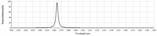
Figure 1. Transmission spectrum of HgS/Na3AlF6 between 1000 and 1200nm
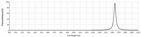
Figure 2. Transmission spectrum of HgS/MgF2 between 900 and 1100nm
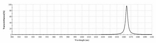
Figure 3. Transmission spectrum of CdS/ Na3AlF6 between 900 and 1100nm
Figure 4 shows the values of transmittance (%) of the dielectric materials at 1064 nm. We can notice that the value of the transmittance (%) is almost the same for all the dielectric materials. Therefore, one may look for other titrated material among these dielectric materials to choose the material that has better characteristics than others.
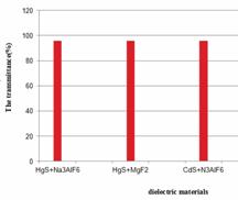
Figure 4. The transmittance (%) of 1064 nm for the dielectric materials
Figure (5) shows the physical thickness for the different dielectric materials. HgS/Na3AlF6, and HgS/MgF2 are thinner than CdS/ Na3AlF6. The dielectric material with the lowest physical thickness has the best characteristics. Therefore, HgS/Na3AlF6 and HgS/MgF2 filters are the best between these materials to be chosen for Nd:YAG Laser.
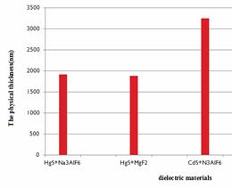
Figure 5. The physical thickness (nm) of the materials
Figure (6) shows the geometric thickness of the used materials. The smallest value of geometric thickness is for HgS/MgF2 which equals 1.77 then for HgS/Na3AlF6 which is equal 1.80 and finally is for CdS/Na3AlF6 which equals 3.05. In thin film coating the smallest geometric thickness provides better coating. Therefore HgS/MgF2 material is the best to act as front Nd:YAG Laser mirror.
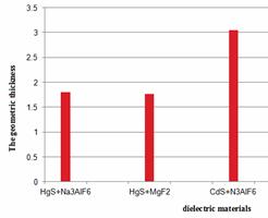
Figure 6. The geometric thickness for different coating materials
Figure (7) shows the optical thickness of the different coating materials. The smallest value of optical thickness is for HgS/MgF2 which equals 14 then for HgS/Na3AlF6 which is equal 14 and finally is for CdS/ Na3AlF6 which equals 22. In thin film coating the smallest optical thickness provide better coating [13]. Therefore, HgS/MgF2, and HgS/Na3AlF6 materials are the best to act as front Nd:YAG laser mirror.
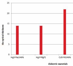
Figure 7. The optical thickness for the used materials
Figure 8 shows a comparison between FWHM for the three coating materials, HgS+Na3AlF6, HgS+MgF2 and CdS/ Na3AlF6. The dielectric material HgS+Na3AlF6 shows smaller (FWHM) compared with HgS+MgF2and CdS/ Na3AlF6. Therefore, the first material is better in this titration.
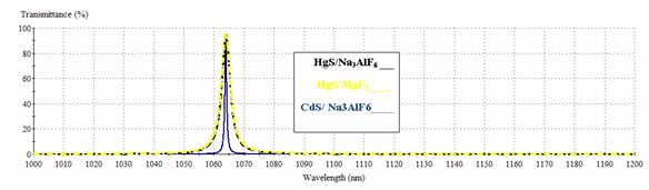
Figure 8. Comparison between the FWHM for the three dielectric materials (HgS+Na3AlF6,
Conclusion
From the obtained results, one can conclude that the best transmittance was achieved with HgS+Na3AlF6 where the transmittance for 1064 nm reaches to 95.74 %. Among the chosen materials one can built Nd:YAG resonator composed of HgS+Na3AlF6 With 11 layers as an output coupler. By applying one quarter of the reference wavelength (1064nm) in the calculations for thin film, the best results for Nd:YAG mirrors resonator were achieved.
References
1. Avraham I. K, Efim G. E., UVB irradiance and atmospheric optical depth at the Dead Sea basin, Renewable Energy, 2012, 48, p. 344-349.
2. Şadan K., Saliha E., Naci E., Suat P., Zafer B., Deposition of MgF2 thin films for antireflection coating by using thermoionic vacuum arc (TVA), Optics Communications, 2012, 285, p. 2373-2376.
3. Angus Macleod H., Thin-Film Optical Filters, CRC Press; 2010, 4th edition, USA
4. Qi Y., Zhu X., Lou Q., Ji J., Dong J., Wei Y., Nd:YAG ceramic laser obtained high slope efficiency of 62% in high power applications, Optics Express, 2005, 13, 8725-8729.
5. Guoqiang X., Dingyuan T., Jian K., Liejia Q., Passively Q-Switched Nd:YAG ceramic laser with GaAs saturable absorber, Proceeding of Pacific Rim Conference on Lasers and Electro-Optics, 2007, p. 1219-1220.
6. Holovský J., Nicolay S., De Wolf S., Ballif C., Effect of the thin-film limit on the measurable optical properties of grapheme, Scientific Reports, 2015, 5, 15684.
7. Svelto R., Principles of Lasers, 5th Edition, Springer, New York, 2009.
8. Barbos C., Blanc-Pelissier D., Fave A., Blanquet E., Crisci A., Fourmond E., Albertini D., Sabac A., Khaled A., Girard P., Lemiti M., Characterization of Al2O3 thin films prepared by thermal ALD, Energy Procedia, 2015, 77, p. 558-564.
9. Ismail A, Abdullah M. J., The structural and optical properties of ZnO thin films prepared at different RF sputtering power. Journal of King Saud University - Science, 2013, 25(3), p. 209-215.
10. Michael I., Larry D., Andrew A., Multiple Scattering of Light by Particles, Cambridge University Press, U. K., 2006.
11. Hall D., The Physics and Technology of Laser Resonators, Taylor and Francis Ltd, U.K., 1999.
12. Tong X. L., Zheng Q. G., Qin Y. X., Optical and electrical properties of GaN/AlN super lattices grown on Si (1 1 1) substrate by pulsed laser deposition, Thin Solid Films, 2003, 217(1-4), p. 28-33.
13. Po-Jen C., Shu-Yuan W., Keh-Chang C., Combined with chemical and thermal post-treatments of titanium, for dye-sensitised solar cell applications, Thin Solid Films, 2010, 519(5), p. 1723-1728.