Effect of casting wall thickness and pouring temperature on residual stress build up in aluminium 6063 casting
Saliu Ojo SEIDU*, Adetunji ONIGBAJUMO
Department of Metallurgical and Materials Engineering, Federal University of Technology, Akure, Ondo State. P.M.B 704
E-mails: seidu2@yahoo.co.uk; ebunoluwabukola@gmail.com
* Corresponding Author: phone: +2347088277396
Abstract
This research work is carried out to determine the residual stress build up on aluminium 6063 (A-6063) casting. The effect of pouring temperature on the induced thermal stress in the A-6063 cast was analyzed at constant thickness. The optimum pouring temperature with less induced thermal stress was used to generate a thermal function for increasing cast thicknesses. Castigliano’s theorem of cutting edge thickness was used by varying thickness with a system of three parallel round bars having the larger thickness at the middle crossed with two perpendicular bars. Pouring temperature from 680ºC to 850ºC was investigated with diameter variation of 20mm, 30mm, 40mm, 50mm and 60mm. It was found out that residual tensile and compressive stress varies with increasing casting temperature. Optimum constant temperature of 720ºC was obtained with minimum induced thermal stress of 18.8475MPa and 37.6951Mpa. A mathematical predictive function was obtained from the relationship between the induced thermal stress and the increasing wall thickness in a linear regression fit. Thermal stress was found to increase with decreasing thickness and increasing pouring temperature. The function would be found useful when designing against failure for A-6063 cast products in stress application.
Keywords
Residual Stress; Aluminium 6063; Castigliano’s theorem; Casting; Failure
Introduction
Pouring temperature determines the temperature distribution, fluidity and built-up of pressure and thermal stresses in casting. Solidification process study according to [1] reveals that hot tearing may be best avoided by pouring at the moderate temperature. The temperature gradient between the mold and the incoming melt causes thermal strain, which induced residual stresses in the cast alloy [2]. Solidification begins as the melt is poured into the mold cavity through the gating system, as the temperature drop bringing about crystals formation in the alloy. It was observed in [3] that melting and pouring conditions directly or indirectly affects the quality of the cast products. The thin parts hinder the free contraction of the thick parts during their solidification and cooling. These regions will induce compressive stresses while the thick walls will have stretching stresses.
The strains that may cause distortion are being developed through the casting solidification and cooling caused by variation in cooling rates between different sections as seen in figure 1. Castings that suffer these variations are subjected to cracks, distortion and structural weaknesses [4].
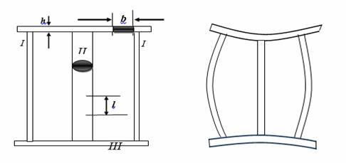
Figure 1. Distortion of members of cast product - (left) before casting (right) after casting
Distortion of casting parts or sections is more pronounced in sand casting techniques. This is mainly because parts are left freely to solidify on their own in the mold and the thermal cycles within the casting are not often controlled which results in thermal stresses leading to the dimensional instability, cold cracking and hot cracking of the parts [5].
During solidification and cooling processes, casting stress is usually formed because of non-uniform phase transformations and contraction rates across castings due to different cooling rates at variable local regions [2]. Phase transformation and contraction are caused due to temperature descent during solidification and cooling of liquid iron. If the phase transformation and contraction are subjected to hindering, casting stress is formed in the casting. The casting stress consists of thermal stress, phase transformation stress and mechanical stress [2].
During the solidification of casting of joint walls with different thickness, the portions with larger section are in still in liquid state, while the zones with small section are already solidified. The thin parts hinder the free contraction of the thin part during their solidification and cooling. Thus, the thin region will have finally compression stresses while the thick will have stretching stresses [6]. The appearance of stresses in two joint bars with different cross section can be analyzed taking into account as shown in Figure 2.
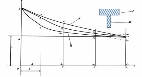
Figure 2. Mechanism of the stresses appearance in two joint bars
In figure 2, the curves I and II correspond to the free linear contraction of the thick and thin bar respectively, if they are not together [7]. When t<t1, both the bar I and II are in plastic state. At the moment t, the free bars I and II will have the lengths ad and bd. Since the two bars are not free, they will have the common length cd; thus, the bar I will shorten plastically with ac and the bar 2 will lengthen also plastically with bc. The stresses will not arise because the bars are plastically deformed. The thin wall is stretched and the thin wall is compressed [7]. When t1<t<t2 the bar 1 is in plastic state and the bar II is elastic state. At the beginning the bars will have the length c1d1. At time t1, the length varies parallel with b1b2 line because the bar 1 is in plastic state and it guides its length after the bar II. At the end of this interval (at t2) the common length will be c2d2. The thin wall is stretched by elastic deformation while the thick wall is plastically compressed [7]. When t>t2, the bars are in elastic state. If the two bars would be independent, the bar I will shorten after the curve c2a3 parallel with the curve a2c3. The bar 2 after the curve c2b3 parallel with b2c3. However, the bars are jointly bound and therefore they will shorten together after c2c3 and finally they have a common length c3d3. The bar 1 will lengthen elastically with a3c3 and the bar2 will shorten elastically with the length b3c3. Thus, after their complete cooling the thicker bar will have a stretching stresses while another will have compression stresses.
The total value of the elastic deformation ε in two joint bars will be:
|
ε = c3a3 + c3b3 = a2c2 + b2c2= b3a3=ε1 + ε2 |
(1) |
where c3a3, c3b3, a2c2, b2c2, b3a3 are dimensions on the joint bars
Between the stresses and the sections of the bars, the following formula can be written:
|
σ1 / σ2 = s1 / s2 |
(2) |
If the elastic modulus E has the same value for the stretching or compression respectively, it results:
|
ε = ε1 / ε1 + ε2 = s1 / s1 + s2 |
(3) |
where
|
ε1 + ε2 = α (T1 + T2) |
(4) |
where α = Specific coefficient of linear contraction in solid state; T1, T2 = Temperature of the two bars when 1 changes its state from plastic to elastic.
Consequently, the stretching or compression stresses will be calculated with the following relationship:
|
ε1 = E α(T1 + T2) (s1 / s1 + s2) |
(5) |
|
σ2 = E α(T1 + T2) (s1 / s1 + s2) |
(6) |
After casting the bars will not cool uniformly. Consequently, stretching stresses will appear in the middle bar and compression stresses in the external bars respectively [7].
The calculation of the internal tension is made by using Castigliano’s theorem. Thus, between the force F and the moment M0 the following relationship can be written:
|
F(l3.2/2I3+l3l.I1) – M0(l3.I+l/I1) = 0 |
(7) |
If the middle bar is sectioned, this will elongate with Δl. The elongation can be determined by the relationship:
|
Δl = 2F/E(l2.3/3I3+ll3.2/I1+2l/S1) – 2M0/E(l3.2/2I3 + l3l/I1) |
(8) |
|
I1 = πd1.4/64 |
(9) |
|
I3 = bh3/12 |
(10) |
where 2l3– is the length of the perpendicular bar; 2l – length of the thin and thick bar; I1 – inertia moment of the thin bar ; I3– inertia moment of the perpendicular bar; S1– area of the thin bar in cross section; S2– area of the thick bar in cross section; E–elastic modulus.
The value of F and M0 determined by the above equations will be used to calculate the internal tension in the bars:
|
σ1 = (F/S1 + Fl3 – M0/W1) |
(11) |
|
σ2 = 2F/S2 |
(12) |
|
σ3 = M0/W3 |
(13) |
where: W1 and W3 are the resistance modulus of the thin and perpendicular bar, respectively;
|
W1 = πd1.3/32 |
(14) |
|
W3 = bh2/6 |
(15) |
where d1– diameter of the thin bar; b, h– the width and the height of the perpendicular bar cross section respectively.
The stresses can produce hot cracks or cold cracks in castings. In order to reduce these undesired effects it becomes necessary to minimize the thermal stresses arising from casting procedure [8].
Material and method
The materials used include, aluminum alloy (A6063) with (99.99%) purity, silica sand, bentonite and parting sand. The equipment used are 10kg capacity gas fired pit furnace, a high precision electronic weighing balance, digital thermocouple, table vice, hack saw and meter rule.
Pattern design
A system of 3 cylindrical bars (2 are of Ø12mm × 30mm and middle bar with varied thickness) bridged by 2 perpendicular square bars (20mm × 20mm × 340mm) were produced with the aid of wooden pattern forming a complex geometry of 5 samples for varied thickness and another of Ø10mm × 300mm small cylindrical bars and Ø45mm × 300mm bridged with square bars of (20mm × 20mm × 165mm) for varied pouring temperature, as shown in the Fig. 3a – 3c.
|
a |
b |
c |
|
|
d |
e |
||

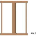
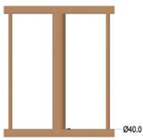
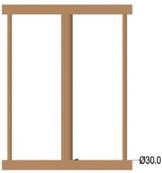
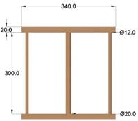
Figure 3. a. Pattern with Ø60mm; b. Pattern with Ø50mm; 3c. Pattern with Ø40mm; 3d. Pattern with Ø30mm; 3e. Pattern with Ø20mm
Figure 4 was use for the variation of temperature at constant wall thickness.
Casting
Aluminum billet was charged into a 10kg crucible furnace for melting. Charge calculations were utilized to evaluate the quantities of melt of aluminum alloy. The metal was heated to melt (660°C) and sufficiently superheated (pouring temperature).The molten metal was deslag and cast into already prepared sand moulds.
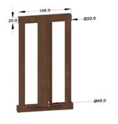
Figure 4. Pattern with Ø45mm
Two (2) samples were cast per melt (pouring temperature and thickness). The same procedure was repeated for the remaining samples. The pouring temperature was varied with the casting done at 680, 720, 750, 800 and 850ºC for the first casting sequence and 720ºC for the second sequence of casting.
Results and discussion
The induced thermal stress is calculated using the Castigliano’s cutting edge analysis. The thermal stress was calculated from the resistance modulus and principle of inertia moment of the bars.
Compressive stresses in the thin bars:
|
σ1 = -(F/s1 + Fl3 - M0/W1) |
(16) |
Tensile stresses in the thick bar:
|
σ2 = (2F/S2) |
(17) |
Tensile Stresses in the perpendicular bars:
|
σ3 = (M0/W3) |
(18) |
where: W1 and W3 are the resistances modulus of the thin and perpendicular bar, respectively
|
W1 = (πd1,3)/32 |
(19) |
|
W3 = bh2/6 |
(20) |
where d1 – diameter of the thin bar;
Effect of varying temperature on induced compressive and tensile stress
Table 1 shows the results of calculation of inertia moment while Table 2 shows the result of induced thermal stress with varying temperature at constant thickness.
Table 1. Result of change in length (Δl), surface area, Force and Moment obtained at constant thickness with varying temperature
|
Sample |
A |
B |
C |
D |
E |
|
Pouring Temperature (ºC) |
680 |
720 |
750 |
800 |
850 |
|
Change in Length Δl (m) |
Short run |
0.001 |
0.002 |
0.003 |
0.004 |
|
Force (KN) |
No value |
14.993 |
29.987 |
44.981 |
59.975 |
|
Moment(KNm) |
No value |
1.236 |
2.437 |
3.710 |
4.947 |
|
**Cast Sample A-E are at 45 mm diameter |
|||||
Table 2. Result of change in length (Δl) and stresses obtained at varying pouring temperature
|
Sample |
A |
B |
C |
D |
E |
|
Pouring Temperature(ºC) |
680 |
720 |
750 |
800 |
850 |
|
Change in Length Δl (m) |
Short run |
0.001 |
0.002 |
0.003 |
0.004 |
|
σ1(MPa) |
No value |
-19.26484 |
-38.52969 |
-57.79454 |
-77.05938 |
|
σ2(MPa) |
No value |
18.8475 |
37.6951 |
56.5426 |
75.3902 |
|
σ3(MPa) |
No value |
54.5154 |
109.0308 |
163.5463 |
218.0617 |
|
**Cast Sample A-E are at 45 mm diameter |
|||||
Figure 4 and 5 shows the response of the thermal compressive and tensile stresses in the thin bars (side members) to the varying pouring temperature, it was observed that the influence of pouring the melt at different temperatures result in increased thermal stresses as the pouring temperature increases [9]. During solidification of joint walls, the portions with larger section are still in liquid state while the zones with small section had already solidified. The thin parts hinder the free contraction of the thick parts during their solidification and cooling. The higher temperature difference in the casting lead to higher stretching stresses in the thick wall, which in turn induce compressive stresses in the thin wall [10].
The observed response of the tensile stresses in the thick bar to the varying pouring is attributed to uneven solidification of the joint walls. The portions with larger section are still in liquid state while the zones with small section had already solidified [10]. The thick parts hinder the free expansion of the thin parts during their solidification and cooling leading to corresponding tensile stress in the cast material [2].
Figure 4. Bar chart showing the compressive stress in thin bar versus pouring temperature
Figure 5. Bar chart showing the tensile stress in thick bar versus pouring temperature
Effect of varying wall thickness on the residual stress
The change in moment and extension in the A-6063 as a function of increasing wall thickness at constant temperature of 720ºC is presented in Table 3. This pouring temperature is used in that it results in the least residual stress (compressive and tensile) in this investigation. The inertia of the different cast material is used to determine the relative strain build up relative to the surface area of the cast sample. The resulting tensile and compressive thermal stress is presented in Table 4.
Figure 6 shows the response of the thermal compressive stresses in the thin bar to the varying thickness of the thick bar at Tp=720ºC, it was observed that increasing the thickness result in decrease in thermal compressive stresses as the pouring temperature is kept constant. According what was obtained earlier in Figure 4, the compressive stress range obtained there within the temperature range of 720ºC to 750ºC is 192.6484MPa to 385.2969MPa which conform with that (19MPa to 403MPa) obtained with varying thickness
Table 3. Result of change in length (Δl), surface area, Force and Moment obtained at constant pouring temperature with varying thickness
|
Sample |
A |
B |
C |
D |
E |
|
Diameter ϴ(m) |
0.02 |
0.03 |
0.04 |
0.05 |
0.06 |
|
Change in Length Δl (m) at Pouring Temperature (720ºC) |
0.0001 |
0.0002 |
0.0005 |
0.0015 |
0.002 |
|
Force (KN) |
42.276 |
30.824 |
13.893 |
5.0529 |
2.0062 |
|
Moment (KNm) |
0.7137 |
0.5203 |
0.2337 |
0.08501 |
0.03375 |
|
Surface area of the Thick bar (m3) |
2.8286·10-3 |
1.9643·10-2
|
1.2571·10-2
|
7.0714·10-4 |
3.1429·10-4
|
Table 4. Result of tensile and compressive tensile stress with varying thickness
|
Sample |
A |
B |
C |
D |
E |
|
Diameter ϴ(m) |
0.02 |
0.03 |
0.04 |
0.05 |
0.06 |
|
Change in Length Δl (m) at Pouring Temperature (720ºC) |
0.0001 |
0.0002 |
0.0005 |
0.0015 |
0.002 |
|
σ1(MPa) |
-403.0867 |
-293.8994 |
-137.1983 |
-49.8992 |
-19.8127 |
|
σ2(MPa) |
29.8927 |
31.3854 |
22.1026 |
14.2911 |
12.7673 |
|
σ3(MPa) |
740.7768 |
540.1901 |
242. 6344 |
88.2465 |
35.0386 |
Thus, these further confirm that casting with good quality and minimal induced thermal stress can be obtained at this pouring temperature range. This effect can be attributed to the adjustment in wall thickness of the joint wall of the casting with an optimum pouring temperature [2]. Thus during solidification of joint walls, the portions with larger section are still in liquid state while the zones with small section had already solidified. The thin parts hinder the free contraction of the thick parts during their solidification and cooling. Thus, induced thermal Compressive stresses increases in joint walls as the different in walls thickness variation increases [9, 11].
Figure 7 shows that thermal stresses increases with increase in thickness at Tp=720ºC. But diameter 0.05m has the highest value (31.3854MPa). Reason being that molten metal splash away from parting line during pouring causing flashes on the side members (thin bars) of the casting component. This causes the thin bar to solidify faster than normal. Induce more buckling (distortion) in the component. Despite fettle, the effect still causes high thermal stress in the casting [11]. Since the stress value still falls within the range as obtained with pouring temperature 720ºC to 750ºC in figure 5. It shows that no matter the wall thickness of the pattern to be cast at 720ºC will enable us to have accommodated bulk residual stress in the casting. This also in accordance with the superheat temperature use for study of mechanical properties of AL6063 according to [9]. Thus, this further confirms that casting with good quality and minimal induced thermal stress can be obtained at this pouring temperature range.
Figure 6. Bar chart showing the compressive stress in thin bar versus diameter of thick bar at constant pouring temperature
Figure 7. Bar chart showing the Tensile stress in thick bar versus thickness at constant pouring temperature
Conclusions
At the end of this investigation, it was found that for Aluminum AL6063, the optimum pouring temperature range is between 720ºC and 750ºC. This is the region where good quality casts are produced with minimum residual stresses.
The pouring temperature which gave the minimum thermal stresses in the casts, is 720ºC with stress value of 18.8475Mpa tensile in the thick bar and -192.6484Mpa compressive in the thin bar. Thus, it can be concluding that the higher the pouring temperature, the higher the induced thermal stresses.
Optimization of this pouring temperature (720ºC) on varying wall thickness (20, 30, 40, 50 and 60mm diameter) produced tensile stresses with the following value (121.763, 14.2911, 22.1026, 29.8927 and 31.3854MPa) respectively.
This also confirms that residual stress build up increases with increased wall thickness even at optimized pouring temperature of 720ºC to 750ºC
Acknowledgements
The authors of these research wishes to acknowledge the technologist of the department of metallurgical and materials engineering, Federal University of Technology, Akure, Ondo State, Nigeria for their relentless effort in the face of seeming difficulties experienced in the course of this work.
The design study, data collection and analysis, decision to publish, and manuscript preparation was a joint effort of both authors.
References
1. Peter B., Introduction to Foundry Technology. Butterworth, 2011, 4th Edition Publisher, Wiley Publisher.
2. Tong S., Liu L., Study and Practice of Decreasing Residual Stress with Residual Heat of Casting, Journal of China Foundry, 2010, 5(2), p. 186-189.
3. Mohsen S. S., Sten J., The Effects of Casting Parameters on Residual Stresses and Microstructure Variations of an Al- Si Cast Alloy, 62nd Annual Denver X-ray Conference (DXC), International Centre for Diffraction Data (ICDD). Westminster, Colorado, U.S.A, 2009, p. 553-560.
4. Parkins R. N., Cowan A., The Mechanism of Residual-Stress Formation in Sand Casting. Journal of the Institute of Metals, 1954, 82, p. 1-8.
5. Celentano D. J., A Large Strain Thermoviscoplastic Formulation for the Solidification of S.G. Cast Iron in a Green Sand Mould, International Journal of Plasticity, 2011, 17(12), p. 1623-1658.
6. Tebedge N., Alpsten G., Tall L., Residual-Stress Measurement by the Sectioning Method, Journal of exposition in Mechanics, 1973, 13(2), p. 88-96.
7. Stefanescu F. L., Neagu G., Materials Casting and Solidification, Practice Aspect. U.P.B. Scientific Bulletin, 2009, Series B. p. 48-54.
8. Wyatt J. E., Berry J. T., Syrotuck D., Johnson A., A Novel Technique for the Determination of Macro-Level Residual Stresses, 5th International Conference on Industrial Tooling, Southampton Institute Conference Centre, U.K. 2008, p. 185-195.
9. Ndaliman M. B., Pius P. A., Behavior of Aluminum Alloy Castings under Different Pouring Temperatures and Speeds, Leonardo Electronic Journal of Practices and Technologies, 2008, 11, p. 71-80.
10. Rossini N. S., Dassisti M., Benyounis K. Y., Olabi A. G., Methods of measuring residual stresses in components. Journal of Materials and Design, 2012, 35, p. 572-588.
11. Shadley J. R., Sorem J. R., Rybicki E. F., A Fourier series back-computation method for the parting-out step in residual stress measurements in pipes, Journal of Pressure Vessel Technology, 1989, 111(3), p. 225-233.